Quick Overview
LJLM is a software for mapping videos, effects, text, and live visual sources onto LED installations and DMX fixtures. It lets you build stages, patch strips and fixtures, play media, layer multiple stages, create sequences, perform live, and control the output through protocols such as Art-Net, sACN, and KiNet.
LED mapping means defining where each LED or fixture element is located in a virtual stage so LJLM knows which part of the media should be sent to it. Instead of treating the installation as a simple list of DMX channels, LJLM treats it as a visual surface. This is what allows you to display images, videos, effects, and layered looks on installations of almost any shape.
LJLM allows dividing your installation into multiple zones and layers called stages. You control the media content independently for each stage. Stages can overlap and they are merged (blended) to generate the result. A common scenario is to create a stage spanning the whole installation to map media across the board. To enable precise control over specific zones, you create smaller stages inside the big stage. Then you activate these zones whenever you want.
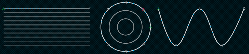
To represent your LED strips and DMX fixtures inside a stage, LJLM has a powerful vector-based editor. This way, you can easily draw many types of shapes, including matrices, loops and curves. LJLM computes the position of each LED based on your drawing.
Computer Requirements
LJLM is compatible with Windows 7 and up, including Windows 8, 10 and 11. x64 and Arm64 are supported.
Minimum
-
Windows 7+, dual core 2 GHz CPU, 2 GB RAM
-
NVIDIA GeForce 600 series or Intel HD Graphics 5500, released after 2013 with OpenGL 3.3 support
Recommended
-
Windows 10 or 11, quad core 3.5 GHz CPU, 8 GB RAM
-
NVIDIA GeForce 900 series or NVIDIA 10 series or better
-
SSD hard drive
The computer requirements depend on your media type. For example, playing multiple HD videos requires a good computer. A rule of thumb is you can play one full HD video @ 30fps for each 2 GHz CPU core. So if you have an Intel i7 4 GHz (4 cores), you should be able to play 8 full HD videos. Increasing the playback speed to 2x means the fps also increases two times and the number of videos you can play simultaneously is roughly divided by two.
The next table shows the approximate number of videos you can play simultaneously at 30 fps depending on your CPU.
| CPU Speed x Cores | Full HD Videos | HD Videos | 640x360 Videos |
|---|---|---|---|
| 2 GHz x 2 | 2 | 4 | 10 |
| 3 GHz x 2 | 3 | 6 | 15 |
| 4 GHz x 2 | 4 | 9 | 20 |
| 2 GHz x 4 | 4 | 9 | 20 |
| 3 GHz x 4 | 6 | 13 | 30 |
| 4 GHz x 4 | 8 | 18 | > 40 |
| 3 GHz x 8 | 10 | 22 | > 40 |
For live video performances, when you want to change the playback speed and go up to 10x, the recommended video resolution is 640x360.
To use the built-in effects, particularly the eye candy effects, the video card will be doing the hard work. If you’re using a laptop, make sure it can sustain a continuous use of the effects without overheating. Usually, an integrated video card can render two eye candy effects. For more effects, you need to have a discrete video card.
About the DMX output, a 1 Gigabit network should be able to handle 2048 universes @ 44fps. For more universes, a supplementary network card and a second Ethernet network are recommended.
Licenses
The LJLM’s licensing system has been built with reliability and simplicity in mind. Basically, once a computer has been activated, it will be able to run LJLM until it dies. No internet connection required, so you can be completely off the grid without worrying about the license.
Each license is registered to one individual or company and covers the activation of the software on a certain number of computers, so long as LJLM is running on one computer at a time. For example, you can activate a show and a backup computer but only one computer can run LJLM at a time.
The license is a simple file that you import once. No hardware dongles are needed, eliminating a whole range of tricky problems: broken dongle, lost dongle, dongle suddenly not detected in the middle of the show, etc.
Your license is tied to one computer at a time and each license includes a set of computer transfers so you can move your license whenever you upgrade or replace your machine. If you ever use up your included transfers, you can buy additional transfers at a small fraction of the license price - only when you actually need them. This keeps LJLM flexible and affordable: you always have access to the latest version, and you only pay for computer transfers when your hardware changes.
To get more DMX universes, you can activate multiple licenses on the same computer. The DMX universes of all licenses will be added.
The Portal allows to easily manage your licenses.
Software Updates
You always have access to the latest and greatest version, free of charge.
To get the updates, go in the Settings/About menu and press the check for updates button. Alternatively, you can go on the LJLM’s website and download the latest version.
https://www.lightjams.com/ljlm/
Definitions
Art-Net: Protocol to transmit DMX over a standard Ethernet network. Designed by and Copyright Artistic Licence Holdings Ltd.
CITP/MSEX: Controller Interface Transport Protocol/Media Server Extension.
DMX: The most common protocol to control lighting fixtures. The full name is DMX512, which stands for Digital Multiplex.
DMX universe: Represents 512 DMX channels. Enough for 170 RGB LEDs (1 LED takes 3 channels, one for red, one for green and one for blue).
FPS: Frames per second. It refers to an output rate for video or DMX.
HDR: High Dynamic Range. In LJLM, HDR mainly refers to higher precision 16-bit image processing and test values, which gives smoother gradients, more headroom for color corrections, and less visible stepping in fades or low-light content when the media type or your LEDs support it.
KiNet: Protocol to transmit DMX over a standard Ethernet network. Designed by Color Kinetics.
LED strip/string: Lighting fixture that may contain many LED elements and have a certain physical length. Some LED strips are flexible and can be bent to create curves and all kind of shapes. LJLM handles all lighting fixtures as if they were strips, giving you a lot of positioning flexibility.
Mapping: Mechanism used to associate a pixel from a media source to a specific lighting fixture element.
Media: Any type of visual content, including videos and pictures.
Network Device Interface (NDI): Protocol to stream live videos over the network. Developed by NewTek - http://NDI.NewTek.com.
Open Sound Control (OSC): Network protocol allowing multimedia apps to communicate. LJLM can be remotely controlled via OSC.
RGB, RGBW, RGBA, RGBWA: Various color components: red, green, blue, white and amber.
sACN: Protocol to transmit DMX over a standard Ethernet network - like Art-Net. More specifically, the E1.31 subset is used for DMX control. Developed by ESTA.
Spout: Real-time video sharing framework for Windows. Similar to Syphon on Mac. http://spout.zeal.co/
Stage: A mapping surface defining the position of the media placeholder and the position of lighting fixtures.
LJLM Tour
Let’s go over the main screens and controls of LJLM.
Home Screen
Welcome! Start a new project or load an existing one. To see the keyboard shortcut keys, press the alt key.
The screenshots for this manual have been taken from the Milan Cortina 2026 project file made for the two cauldrons. Thanks to LED Creative for this.
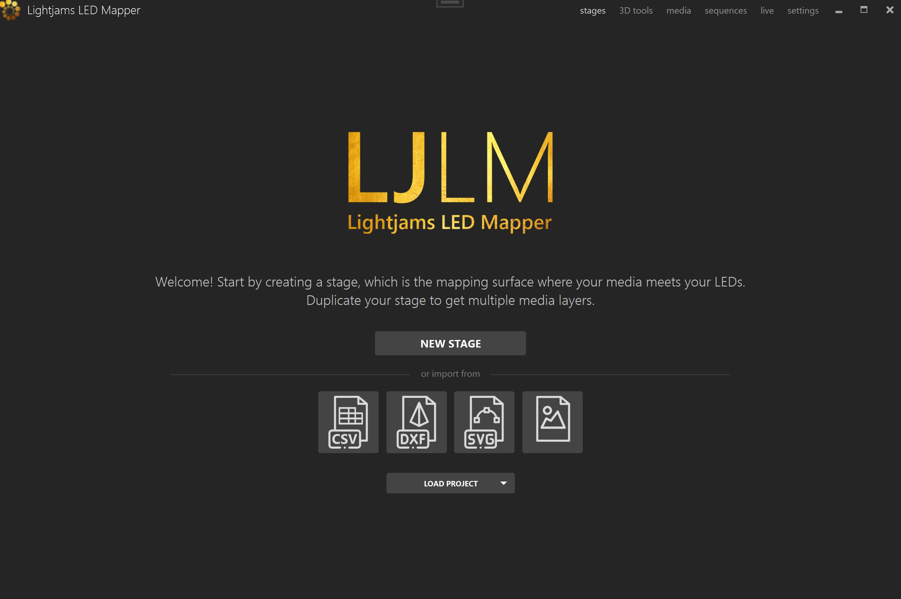
New stage (alt-N)
Load project (ctrl-O)
Recent projects (down arrow)
Import CSV
Import DXF
Import SVG
Import image
Media (alt-M)
Sequences (alt-U)
Live (alt-L)
Settings (alt-I)
New Stage Dialog
A rule of thumb is to create a stage with dimensions respecting the aspect ratio of your media. Then you’ll position your LED strips on it to create the mapping. For example, you can create a full HD stage - which has a rectangular aspect ratio - to fit your media sources, and then map a 20x20 square LED array on it.
You can easily change the dimensions later, so don’t worry. The minimum recommended size is 320x180. Smaller than this size, you’ll need to constantly work at a very high zoom level, which isn’t very convenient. So it’s better to use a higher size and let LJLM scale your media.
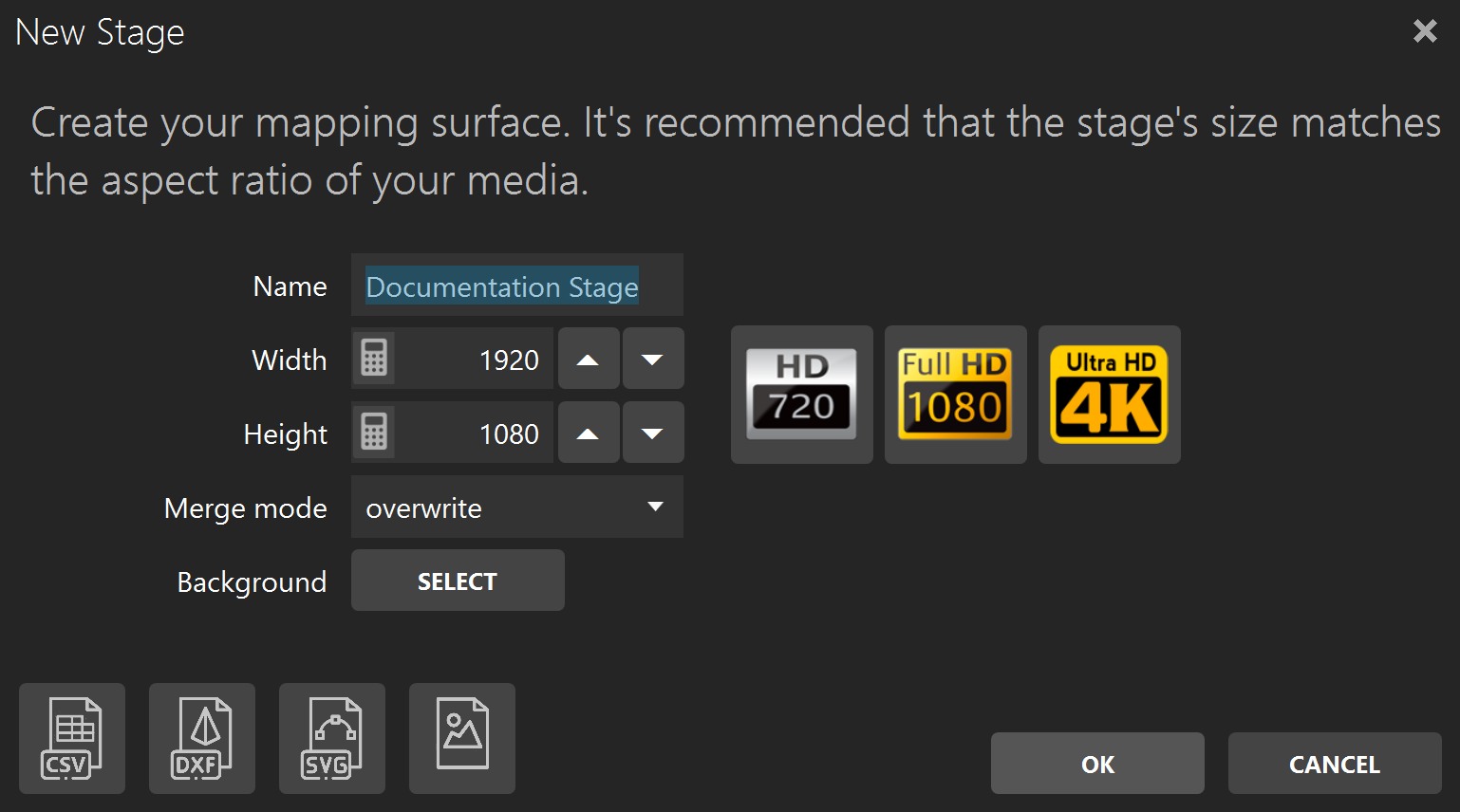
Name
Width, Height
Full HD, HD buttons
Merge mode
Background
To help you position the strips like they are in the real world, use a picture of your installation as the stage’s background (see Stage Tab). No pictures handy? Use your phone’s camera to get one!
Stages
Shortcut key: alt-S
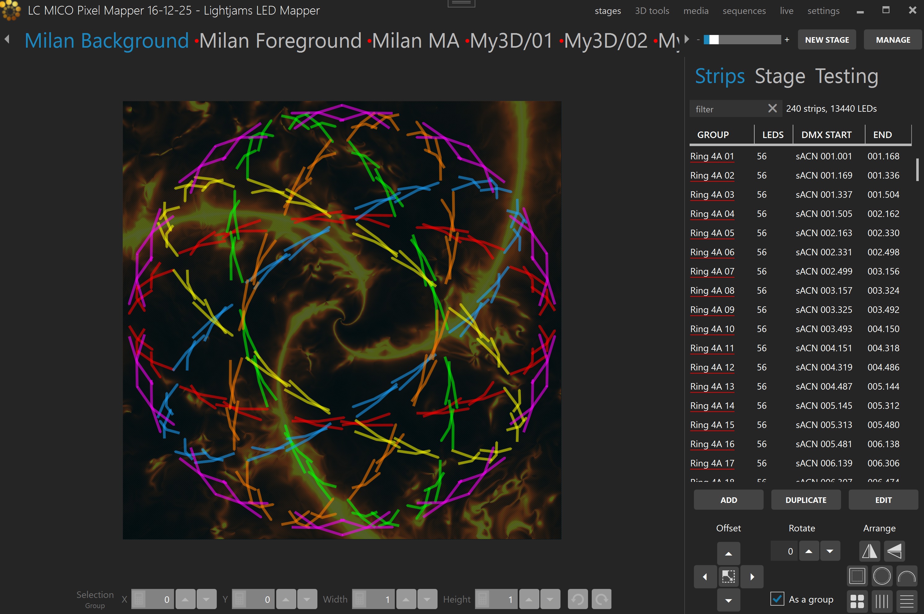
You can create as many stages as you want. Generally, you’ll want an overall stage corresponding to the whole installation and multiple individual stages to target specific zones. The overall stage allows you to map content across the board. Then the other stages allow you to override specific parts of your installation whenever you want. You can select the current stage by clicking its name at the top.
Different effects may demand different mapping layouts. One goal of the mapping is to ease the content creation. So don’t hesitate creating multiple stages with the same LED strips but positioned in different ways.
Stage Syncing
All stages using the same media slot are considered to be synced. You can still change the individual stage output parameters like the intensity and the color filter, but the media content is the same on all synced stages. When applicable to the media type, the media playback speed is determined by the maximum speed of all stages using this media.
To play the same video file on multiple stages but at different speeds, load the video file in multiple media slots. Then use a different media slot for each stage.
Stage Merging and Layering
When multiple stages contain the same LED strips, a merge occurs following the order shown in the Stages Manager. The stages are merged from left to right in that list. This allows creating complex visuals by layering multiple stages on top of each other. You can target specific zones by creating stages with only a subset of all strips or with parts of the strips outside the stage. A stage must be activated (a media is selected and the stage’s intensity is greater than 0) otherwise it is considered to be transparent and will not be part of the merge.
The merge modes are:
Overwrite
Multiply
Screen
Overlay
Darken
Lighten
Difference
Add
Subtract
Black key
IntensityCrossFade
IntensityWhiteFade
To easily target specific zones of an installation, first create the overall mapping then select the strips corresponding to the individual zones and right-click in the Strip List to access the new stages from strips menu.
Edit Zone
You can position your strips as they are in the real world or based on the effect you want to create with your media.
A strip has start (green) and end (red) control points indicating the direction of the patch. Multiple intermediate control points can be used to create various shapes. You can bundle multiple strips together to simplify the handling of complex shapes.
You can position parts of your strips outside the stage. In this case, the LEDs outside the stage will not be mapped. This is a common scenario when using the same strips in multiple stages and you want to target specific parts in each stage.
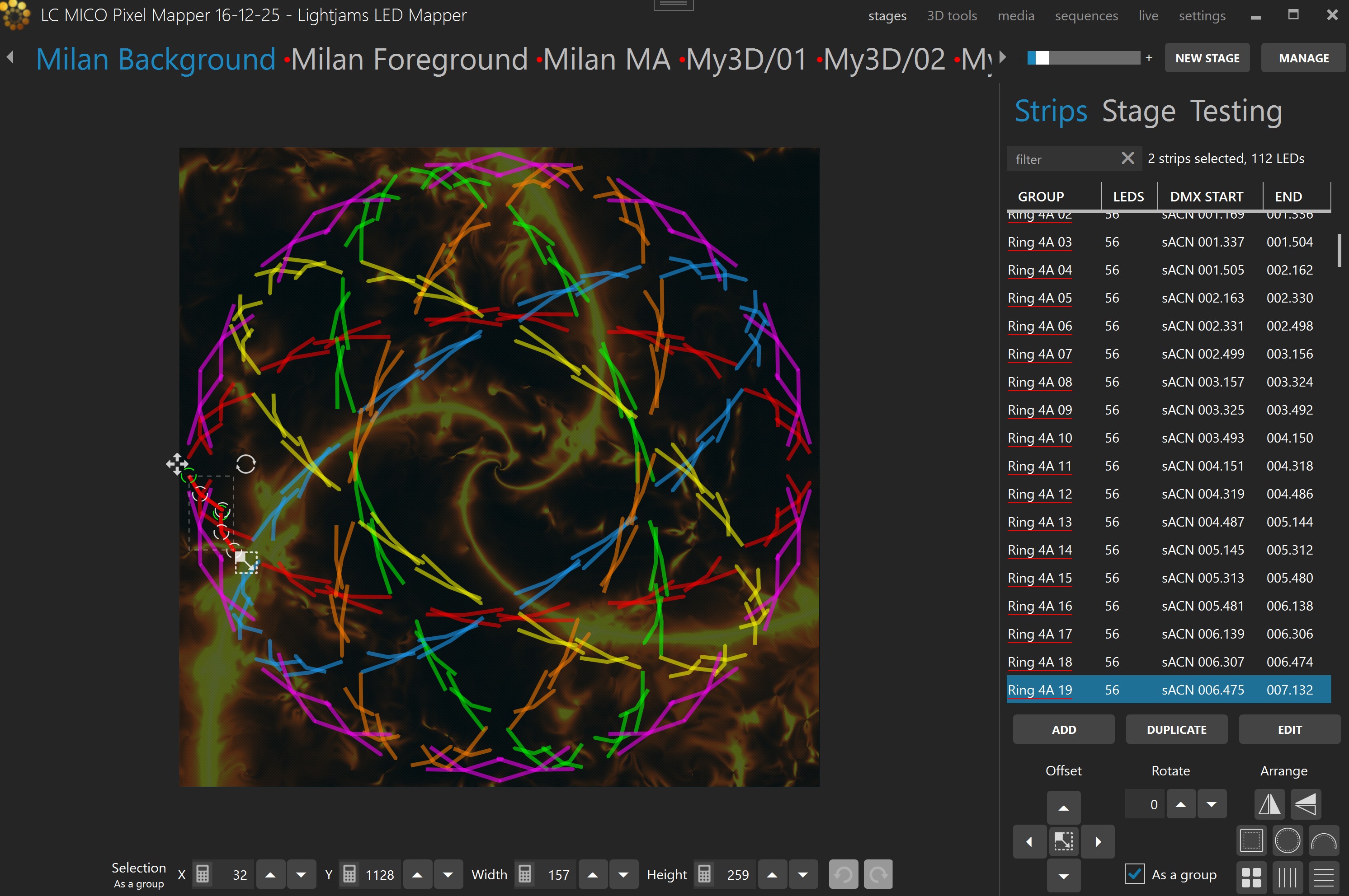
Select strips/Deselect all (ctrl-d)
Move a control point
Move selected strips
Arrange: Flip X / Flip Y
Arrange: Square / Circle / Arch
Arrange: Grid
Arrange: Equal horizontal / vertical spacing
Add a control point
Delete a control point
Bundle/Unbundle strips (ctrl-b, ctrl-shift-b)
Move around the stage
Zoom in/out (ctrl-plus, ctrl-minus, ctrl-0, ctrl+mousewheel)
Show individual LED positions
Copy/paste strips (ctrl-c ,ctrl-v)
Delete selected strips (ctrl-delete)
Undo (ctrl-z), Redo (ctrl-y)
As a group
Strips Tab
Shortcut key: alt-P
Strip List
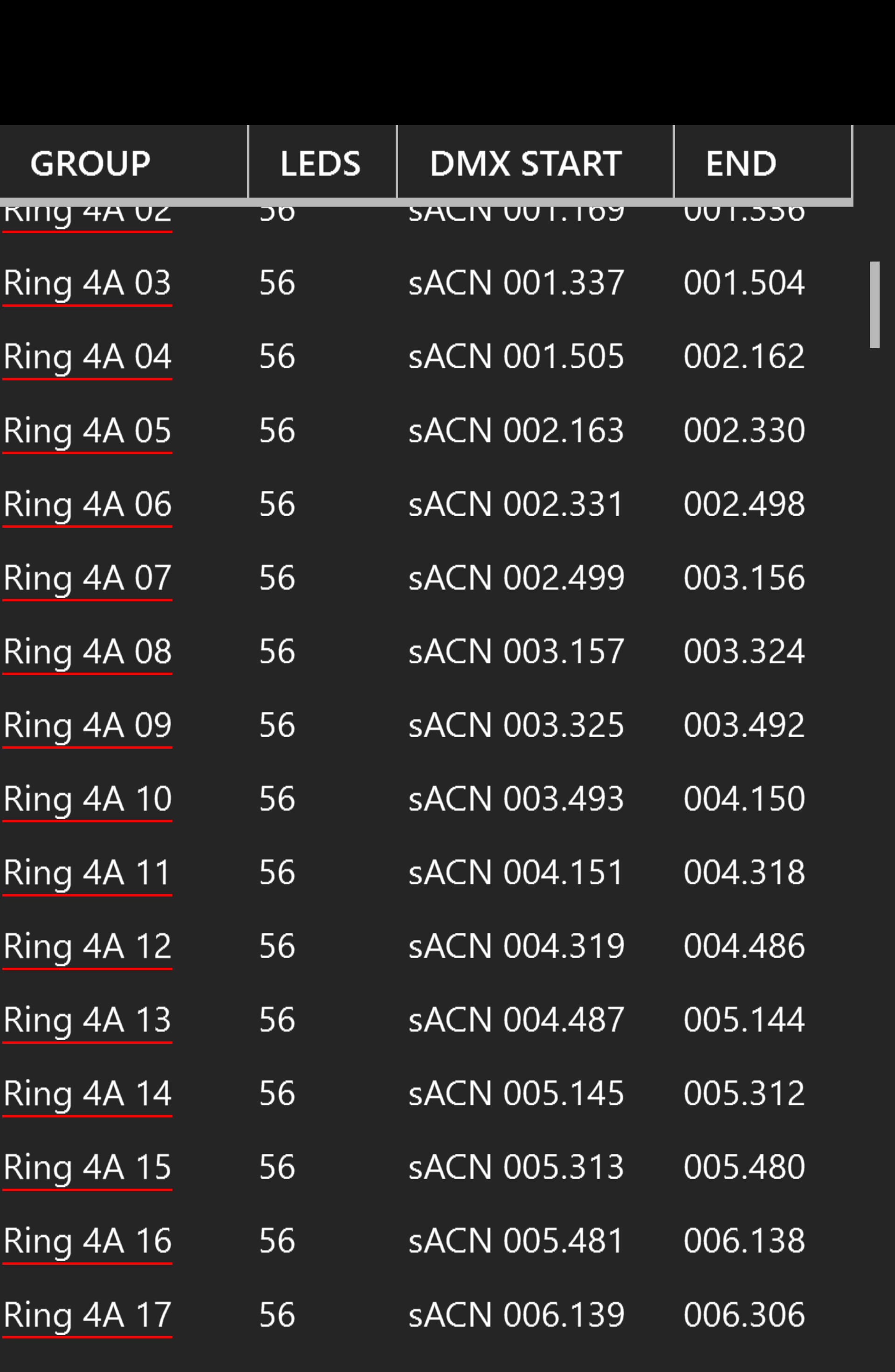
The strips for the current stage are shown in this list. Select one or multiple strips in the list to also select them in the edit zone. You can click the column headers to sort. Type text in the filter box to filter based on the group names. Double-clicking a row focuses the corresponding strip in the editor, and the Go to selection command centers the editor on the current selection.
The strip list context menu includes:
Select all / Deselect / Invert selection
Select even
Go to selection
Copy / Paste
Paste strip settings / Paste strip shape
Delete
Bundle / Unbundle
Split / Join
Adjust LED count and length
New stages from strips
Use the group and sub-group fields wisely in order to use the filter box and quickly select the strips you want.
New stages from strips
This submenu creates new stages from the currently selected strips. LJLM may ask you to confirm the strip order first, because some options depend on the order of the selection.
One stage per strip
One stage per strip, keep positions
One stage per strip, all lines
All strips in a new stage (copy)
All strips on one line (back to back)
Each strip on a new line
Each strip on a new stretched line
Each strip collapsed on a new point
Add Strips Dialog (Patching)
Shortcut key: alt-A
Quickly patch your strips and lighting fixtures to create arrays and any shapes you can imagine. Multiple LED types (or color types) are supported, including RGB, RGBW, RGBA, RGBAW/RGBWA and white (dimmers) in multiple configurable color temperatures like WWA. Most color component orders (GRB, BGR, etc.) are supported. For lighting fixtures supporting high precision colors, 16 bit color depth can be used via the RGB16, GRB16, RGBA16, RGBW16 and White16 types. RGBWmax activates all channels (RGB+white) when white is needed for maximum brightness.
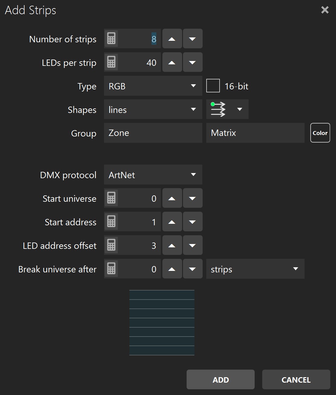
Number of strips
LEDs per strip
Type
Shapes
Patching direction
Group and sub-group
DMX protocol
Start universe
Start address
LED address offset
Break universe after
You’ve got the patching direction wrong? No problem. You can easily flip your strips horizontally and vertically later. For snake mode, right-click in the strip list and use the select odd/even option.
Want to control more complex DMX fixtures like moving heads? Let say your moving head has 20 channels and the RGB channels start at 3. In LJLM, patch it with a start address of 3 and a LED address offset of 20. LJLM will send 0 for the unused channels, which allows merging the DMX data from LJLM with the DMX data from a console. The console should provide the values for the pan and tilt and the all other channels except the RGB.
Whites! You can get a more accurate preview by using the right type of white LED type. Use the WhiteCool, WhiteNeutral, WhiteWarm and WWA (cool, neutral and warm whites) LED types. Unlike the White LED type which takes the perceived brightness of the media as its value, you get finer control with the other whites.
Pixel Types
| LED Type | Detail | Remark |
|---|---|---|
| RGB, RBG, BGR, BRG, GBR, GRB | Red, green and blue. | |
| CMY | Cyan, magenta and yellow. | Use this when your fixture is patched as subtractive CMY color channels instead of RGB. |
| RGBW and all supported component orders | Red, green, blue and white. | The white is automatically activated based on the saturation of the media color. The less saturated the color is, the more the white LED is activated. As the white is activated, the RGB LED levels are reduced proportionally until only the white LED is active for a pure white color. |
| RGBWmax | Red, green, blue and white. | The white activation is calculated like for RGBW but the RGB LEDs aren’t reduced proportionally. The result is that when a pure white color is needed, all RGBW LEDs are activated. While it gives a maximum brightness, it also takes more power. |
| RGBA | Red, green, blue and amber. | The amber LED is automatically activated the closer the media color is to amber. As the amber is activated, the RGB LED levels are reduced proportionally until only the amber LED is active for a pure amber color. |
| RGBAW, RGBWA | Red, green, blue, amber and white. | The white and amber LEDs are activated following the same recipe as for RGBW and RGBA. |
| RGBWX | Red, green, blue and two additional white channels. | This type is for RGB plus two white colors. LJLM controls only the RGB channels and skips the two white channels. |
| White | White or one color component only. | The activation level is based on the perceived brightness of the media color (using the luma calculation). |
| WhiteCool | White cool. | Special type of cool white LED that you can use to get a more accurate preview in the stage monitor. The activation is based on the blue level of the media color. |
| WhiteNeutral | White neutral. | Special type of neutral white LED that you can use to get a more accurate preview in the stage monitor. The activation is based on the green level of the media color. |
| WhiteWarm | White warm or amber. | Special type of warm white LED that you can use to get a more accurate preview in the stage monitor. The activation is based on the red level of the media color. |
| WWA | White cool, white neutral and white warm/amber. | There are 3 types of whites and you’ll get an accurate preview in the stage monitor. The white cool activation is based on the blue level of the media color, the neutral on the green and the warm on the red. |
| WAW | White cool, white warm/amber and neutral white. | See WWA. |
| AWW | White warm/amber, neutral white and white cool. | See WWA. |
| 16-bit option | High resolution 16-bit per color component. | 16-bit is a separate option in the strip dialogs instead of being part of the LED type name. When enabled, LJLM supports end-to-end 16-bit precision from supported media sources through the internal engine and remote control to the DMX output. See Media Types. |
For the color temperature settings to get a more accurate stage monitor preview, see Colors.
Duplicate Strips Dialog
Shortcut key: alt-D
Copy the selected strips and create new strips by applying certain transformations.
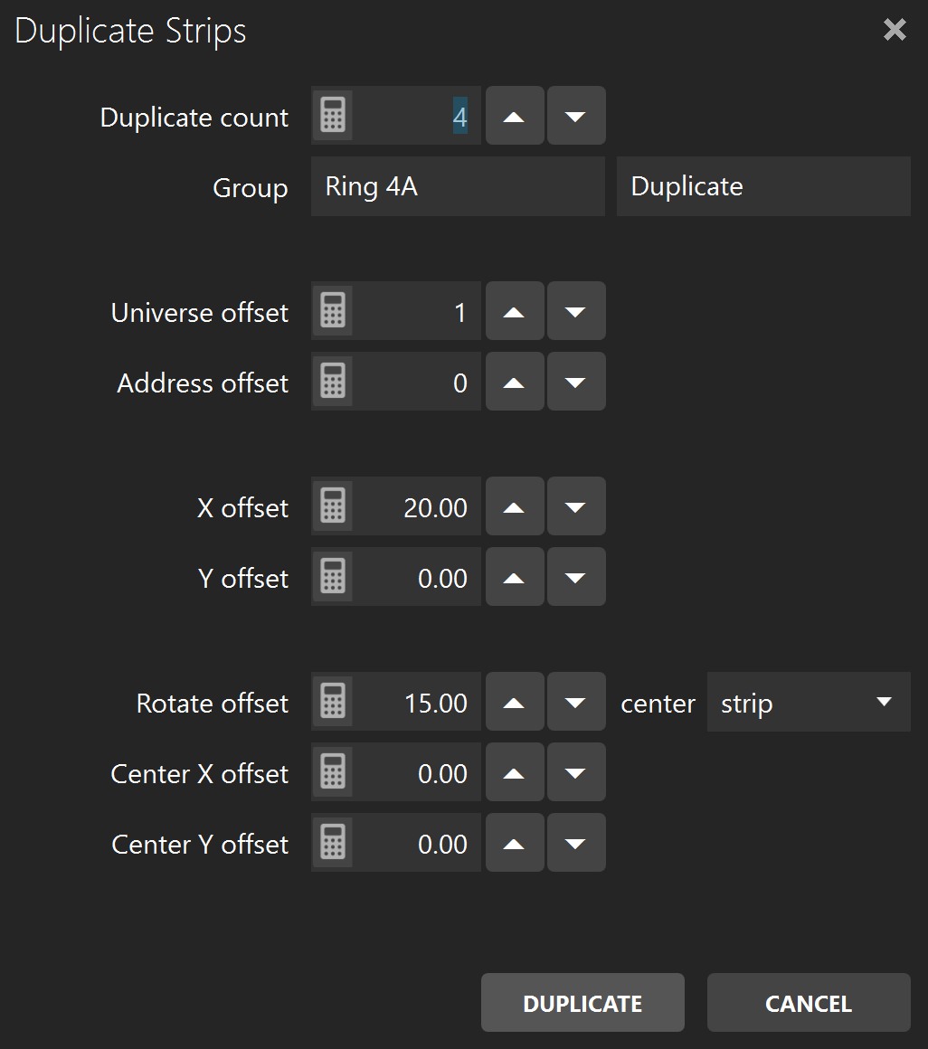
Number of duplicates
Group and sub-group
Universe offset
Address offset
X offset
Y offset
Rotate offset
Rotate center, offset X, offset Y
When you’re in the design phase of the lighting installation, keep in mind the duplicate options. They allow creating complex shapes by copying simple elements. This is a real time saver.
To make sure certain strips always stay together, use the bundle feature. You can create complex shapes by combining multiple simple elements. See the bundle/unbundle options in the Edit Zone.
To copy strips to another stage, select your strips and use the copy (ctrl-c) and paste (ctrl-v) keyboard shortcuts. You can also right-click in the Strip List to see all options.
Edit Strips Dialog
Shortcut key: alt-E
Edit the selected strips and allow changing the patch.
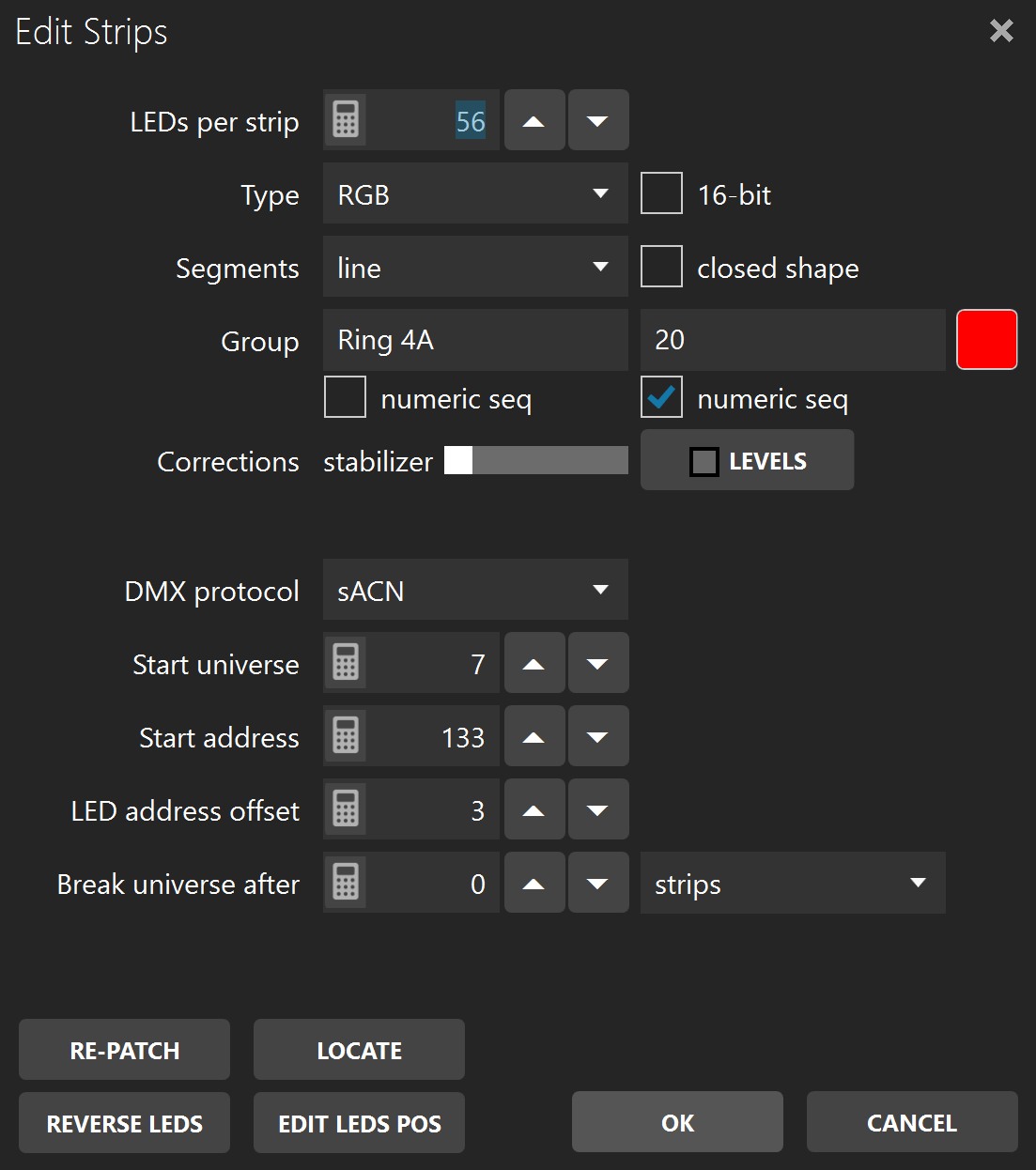
LEDs per strip
Type
Segments
Closed shape
1st LED position
Group – primary, secondary
Numeric seq.
Corrections / Stabilizer
DMX protocol
Start universe
Start address
LED address offset
Break universe after
Apply changes to other stages
Re-Patch (alt-P)
Locate (alt-C)
Reverse LEDs (alt-R)
Edit LED Pos (alt-D)
Levels window
Intensity
Temperature
Tint
Black threshold
Gamma correction
Reset
Offset/Resize Strips Dialog
Shortcut key: alt-O
Precisely change the position and size of the selected strips.
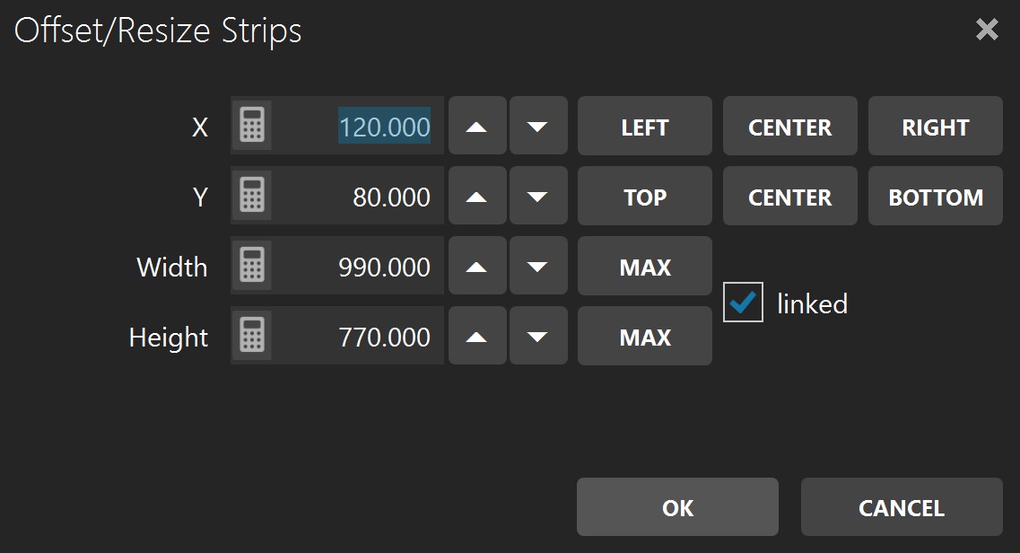
X
Y
Width
Height
Linked option
Right-click in a numeric box and move the mouse left/right to quickly change the value.
Stage Tab
Shortcut key: alt-g
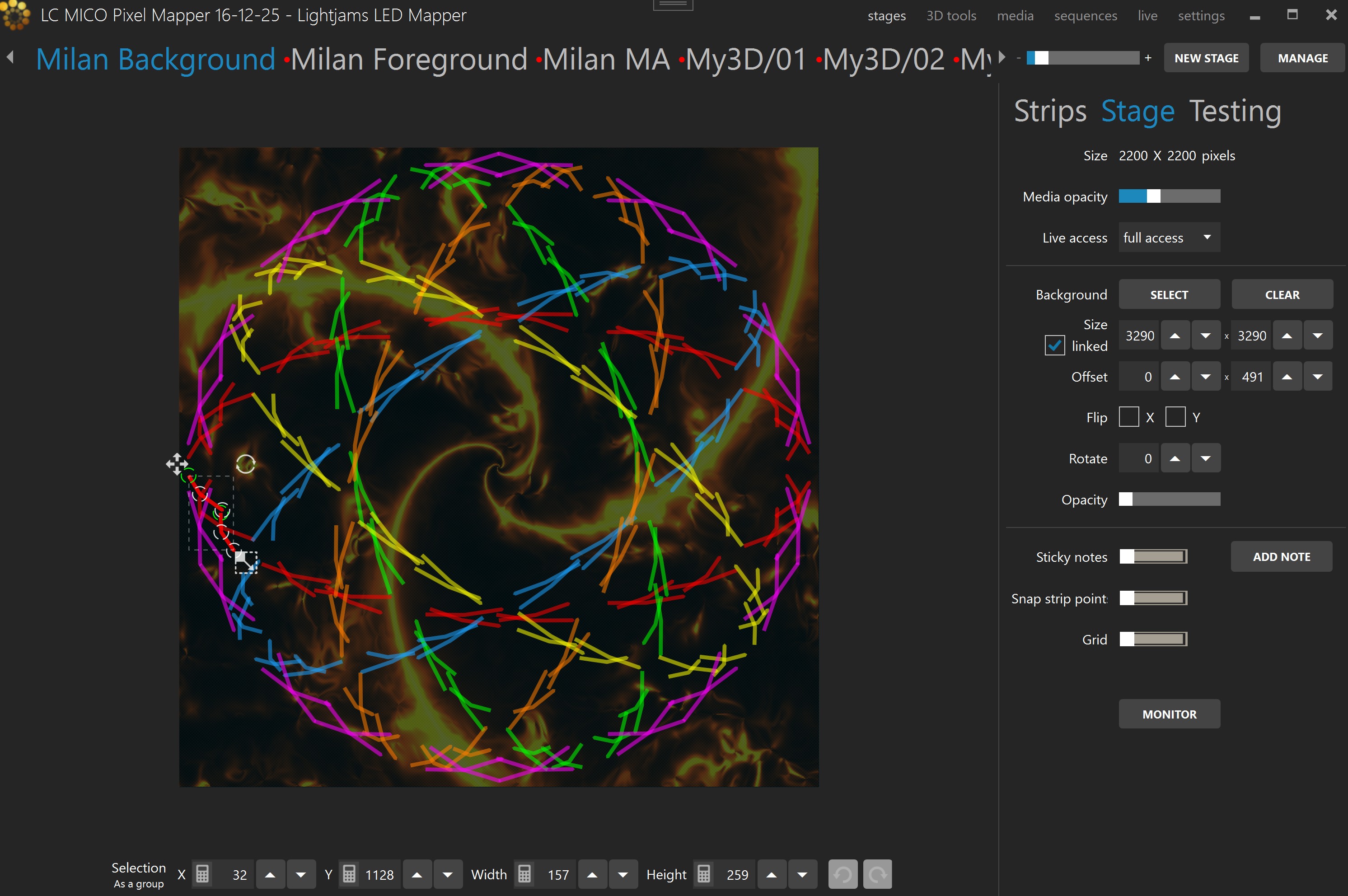
Size
Media opacity
Live access
Background
Size, offset, flip and rotate
Opacity
Sticky notes
Snap strip points (ctrl-P)
Grid (ctrl-G)
Monitor (alt-O)
LED image
LEDs CSV
When you are editing and zoomed in very closely, if media is playing in the preview, your computer may have a hard time. To help it, disable the preview by setting the media opacity to 0%.
Here’s the monitor window. You can see the result of the stage only or after all stages have been merged. When you don’t have access to the real fixtures, this is an indispensable tool while creating effects. Alternatively, you can use any 3rd party visualizer able to receive the LED rendering via NDI (see NDI output in the Stages Manager) or supporting Art-Net or sACN.

Try reducing the stage’s size and see if the output is still good. Also reduce your videos and other media size accordingly to potentially save a lot of CPU. High resolution media is not always a good thing!
Testing Tab
Shortcut key: alt-T
Quickly test the mapping by generating a rectangle that you can move over the strips.
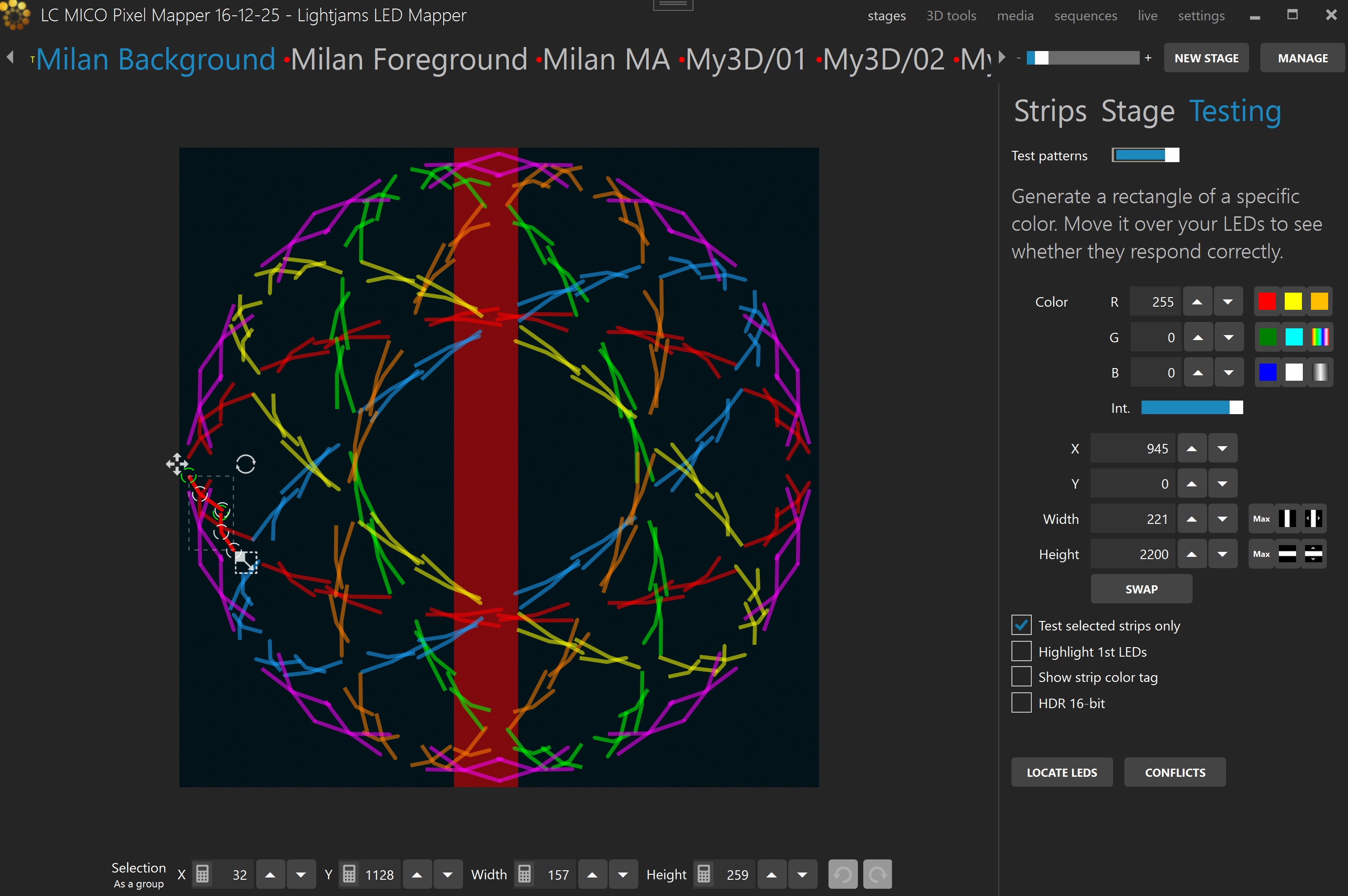
Test patterns On/Off switch
Color
X, Y
Width, Height
Swap
Test selected strips only
If checked, only the selected strips in the Strips Tab will be under test. The other strips will all be off.
Highlight 1st LEDs
Show strip color tag
HDR 16-bit
Locate LEDs
Conflicts
Reduce the width and height of the testing rectangle and drag the rectangle around the stage. This way, you can see if the patch order is right. For example, if dragging the rectangle from left to right makes the LEDs go on from right to left, then you know you need to flip them horizontally. To do so, go in the Strips Tab and click the Flip X button.
Quickly test the red, green and blue component order of your LEDs by generating a pure red, pure green and pure blue test. For each test, note the color of your LEDs. If you’re not getting a RGB order, edit your LED strips and select the LED type corresponding to the order you’ve observed (BGR, GRB, GBR…).
While the testing mode is active, the DMX is constantly being outputted at the full output rate, even when there’s no change. This is handy while you’re configuring your LED controllers and want to see if it’s working. This is also a good way to test whether your network supports the load.
Use the “test selected strips only” option, go in the Strips Tab and change the selection in the strip list. This is similar to traditional lighting consoles locate function.
Stages Manager
Shortcut key: alt-N
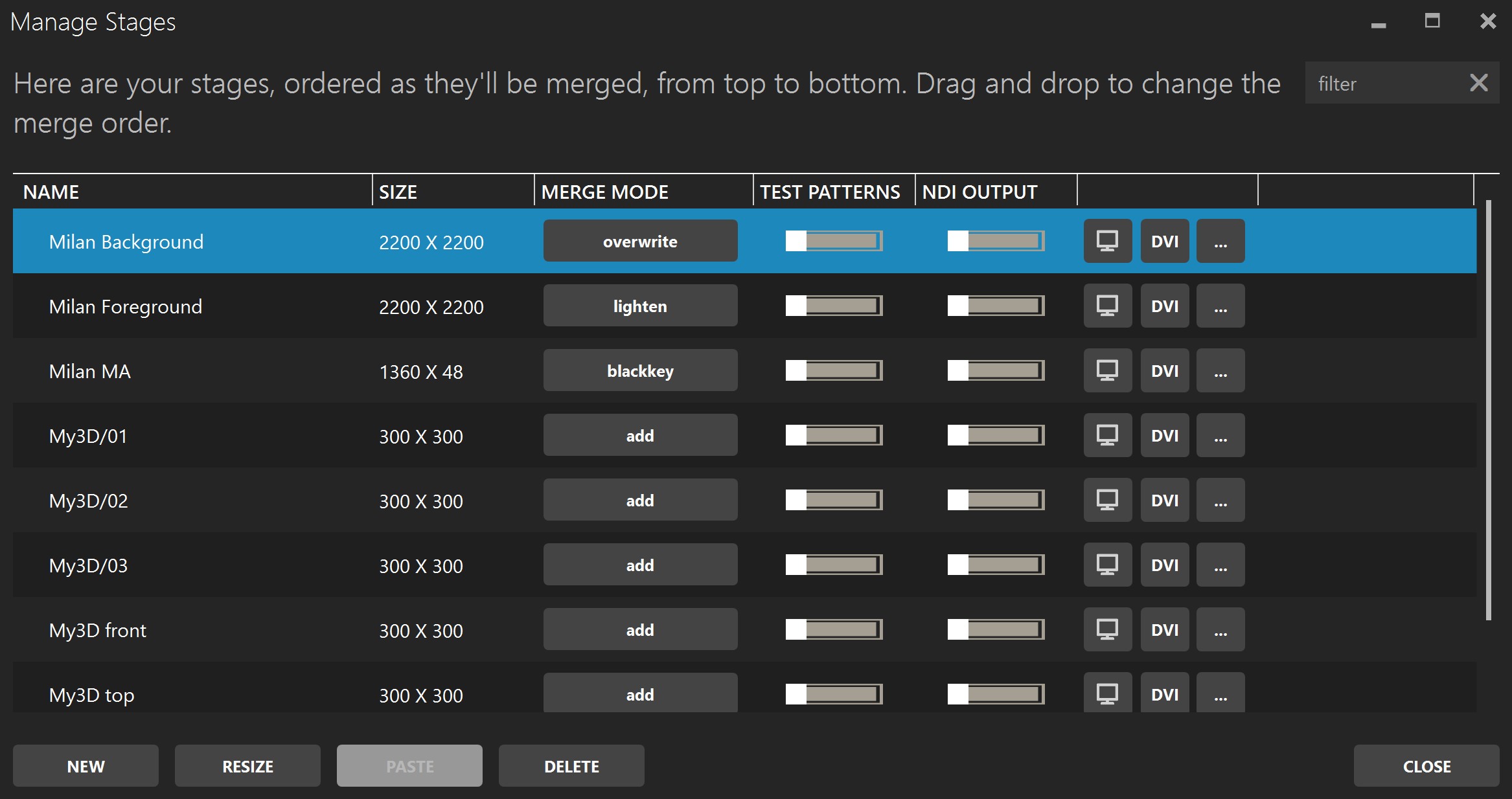
Select multiple stages in the list to modify them all at once. The list is ordered from top to bottom as stages are merged. Drag and drop stages to reorder them.
Name
Size
Merge mode
Test patterns
NDI output
Monitor
DVI
... button
Duplicate
Copy
Export LEDs position image
Export LEDs csv
New
Resize
Paste
Delete
3D
Shortcut key: alt-3
A 3D structure is composed of multiple stages layered on top of each other. Everything you already know about stages can be applied to 3D, including merging, media and remote control.

New 3D
Home (ctrl-0), front (ctrl-F), top (ctrl-U), side (ctrl-R or ctrl-L)
Stage list
Reverse (alt-R)
3D monitor (alt-O)
Select stages (alt-A)
Rename
Resize
Delete
Stack axis
Projection
Media Library
Shortcut key: alt-M
You can manage your media and see what’s active. Up to 999 media items can be loaded. The media library has both a grid view and a list view. In grid view, you can select multiple media items at once. To add new media, click the ✚ icon on an empty slot.
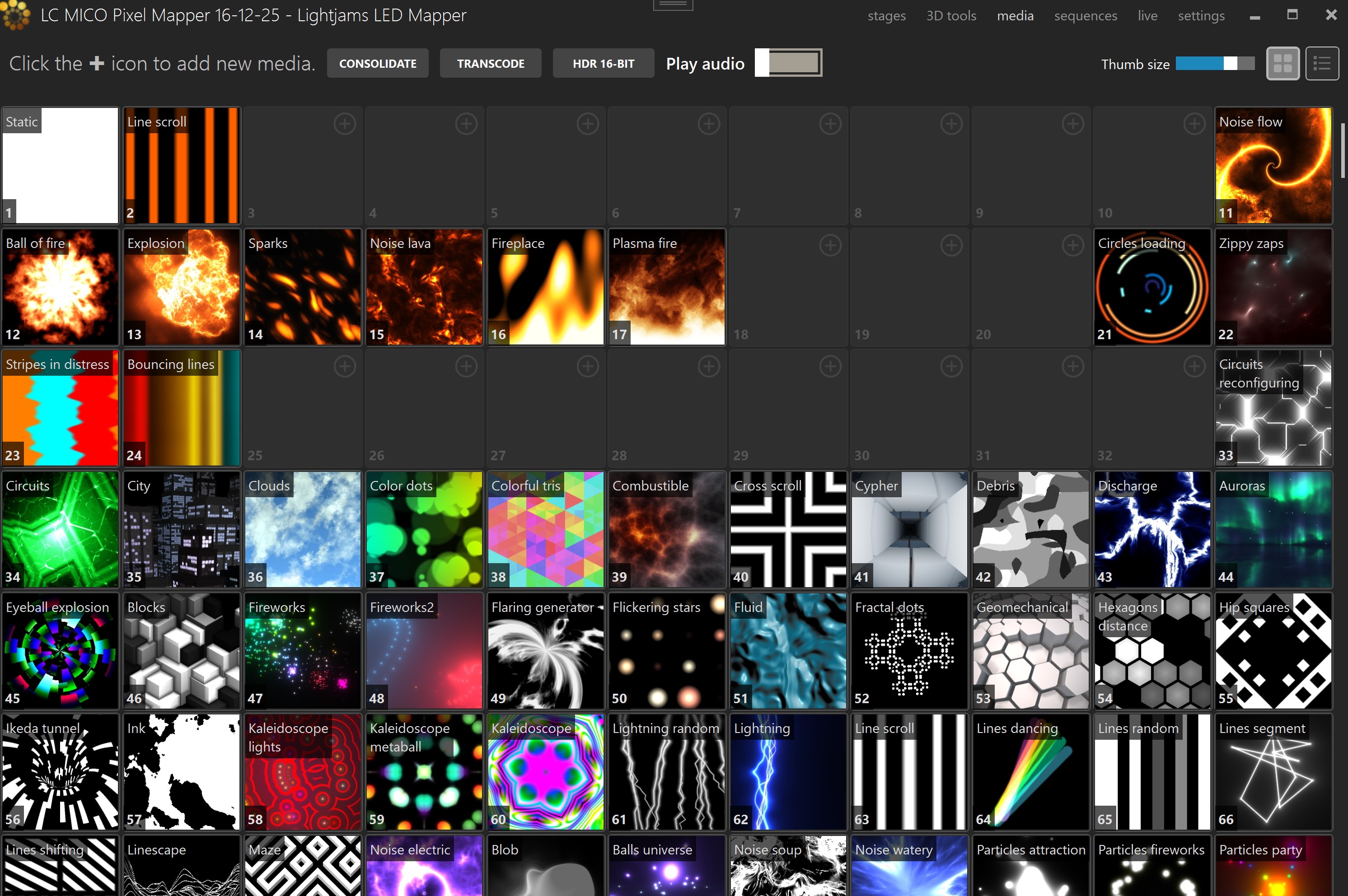
Shared Controls
Add media
Grid view / List view
HDR 16-bit
Consolidate
Transcode
Play audio
Monitor
Delete / Clear slot
Playback position indicator
Swap items and reorder
Grid View
The grid view shows one media slot per square thumbnail. It is optimized for browsing visually and for selecting many slots at once.
Thumb size
Multi-selection
Empty slots
Thumbnail overlay
Grid view context menu
Single-item context actions
Reorder
List View
The list view shows one row per media slot with more details and direct row controls.
Row layout
Empty slots
Monitor button
Delete button
More... button
Video rows
Image rows
Live, text, effects, Spout, NDI and DMX bitmap rows
Reorder
Media Types
The following media source types can be loaded into the media library depending on your workflow.
High bit depth and HDR output
LJLM fully supports end-to-end high precision rendering for LED installations that can display more than 8 bits per color component. LJLM preserves the extra precision from supported media sources, through the internal mixing and compositing engine, through transitions and color processing, and all the way to the DMX output.
This is especially useful for high-end LED products and drivers that support fine color control, because it gives smoother fades, cleaner gradients, better low-level dimming and less visible stepping. LJLM also supports 16-bit stage and group control in the advanced remote control modes for parameters such as intensity, color filters and media mix position.
Not every media source carries the same precision. Some are 8-bit, while others can provide 10-bit, 12-bit or 16-bit data. The following sections mention the relevant support for each media type.
Video Files (with or without audio)
Most video formats are supported when the appropriate DirectShow video codecs are installed. By default, LJLM can play these files: .mov, .avi, .wmv, .mpeg, .mp4, .mp2, .mkv, .webm, .ogv and .ogg. There’s no video size and resolution limits. The audio track is played back on the default sound device. If not needed, you can remove the audio by using the transcode button.
The recommended video format is MPEG4 in an avi file. For smaller files at the expense of a higher CPU usage, you can use H264 in an avi file.
Video playback supports HDR and high bit depth workflows, including 10-bit and 12-bit sources such as HDR10 when supported by the file and decoder path. This allows video content to feed the high precision internal engine and high precision LED output when the rest of the pipeline is configured accordingly.
Picture Files
Use images like bmp, jpeg, gif (animated or not) and png.
Images also support 16-bit workflows where applicable, which is useful for gradients, masks, still HDR content and other static material that benefits from higher precision before being mapped to LEDs.
Effects
The built-in effects give you pixel-perfect and configurable visuals. There are 100+ effects available, including eye candy effects, and many effect parameters can be remotely controlled.
Built-in eye candy effects and GLSL shader based effects support 16-bit rendering, so procedural content can fully benefit from LJLM’s high precision internal engine and 16-bit LED output.
Custom GLSL Shaders and AI Assistant
LJLM also lets you create your own eye candy effects by writing a GLSL shader. All built-in eye candy effects can be edited (right-click on an effect to see the option in the menu) and new effects can be created by clicking the + button on an empty media slot. Custom shaders behave like media items and can be edited in the built-in GLSL editor.
When creating a new effect, the default GLSL code along with many comments will tell you everything about what you can do. But basically, you can define the sliders you want to use as parameters and you have access to the full audio data in real-time.
The built-in AI assistant can help explain, fix and extend shader code. It can work with multiple providers, including local LLM setups. The supported provider presets include OpenAI, Ollama (local), LM Studio (local), GitHub Models, OpenRouter and a custom endpoint. The assistant settings let you configure the provider, base URL, API key when required, model name, additional model parameters and test the connection.
The assistant can use the full shader code, the current selection and the last compilation error as context. It can answer questions, suggest changes and return updated shader code that you can choose to apply back into the editor.
Custom GLSL shaders are part of the same 16-bit capable rendering path, which means they are suitable for generating true high precision content for compatible LED types instead of only standard 8-bit visuals.
Capture Devices
Use live videos captured with a video card input or a connected camera like a webcam. Any DirectX/DirectShow compatible hardware and software are supported.
Magewell capture cards are known to work very well with LJLM. Other manufacturers often used successfully on Windows include Datapath, AJA, AVerMedia, Osprey/Visual Connectivity, YUAN, and some Epiphan devices. Some Blackmagic devices can work, but DirectShow compatibility is more limited, especially for 4K capture. Actual compatibility depends on the specific model and installed driver.
Screen Capture
Capture any part of your screen and use it as a media in LJLM. For example, play a video on Youtube and map it to your LEDs. Another utility is to capture your video editor (like Adobe After Effects) preview zone and let LJLM generate a LED preview in real-time to assist your content creation. This avoids having to render your video before trying it in LJLM.
Screen Capture Dominant Colors
Capture any part of your screen and extract the dominant colors. This is useful to do color matching between any kind of content and your LEDs.
Texts
Generate scrolling text with various fonts.
Spout (v. 2.007)
Use live videos generated by the most common video frameworks and VJ software. This includes Resolume, Ableton Live, Processing, Max/Msp, TouchDesigner, Cinder, OpenFramework, VVVV, Isadora, After Effects, Mapio, Unity3D and more. The Spout integration gives you total control over the content and is the way to go when you want interactive visuals.
Spout supports 16-bit workflows in LJLM, making it a strong option when you want to feed high precision generative or interactive visuals into a 16-bit LED pipeline.
Network Device Interface (NDI v. 6.1)
Receive live video streams via the network, as commonly used in professional live show productions. Easily connect LJLM to a multitude of NDI compatible hardware and software, including capture cards, IP cameras and video over the cloud. NDI has been developed by NewTek - http://NDI.NewTek.com.
NDI support includes 10-bit workflows, which is useful when receiving higher precision live video feeds and carrying that extra precision into LJLM’s internal engine and on to compatible LED outputs.
MJPEG Streams
It’s the most basic way to receive video streams via the network. If your IP camera doesn’t support the more complete NDI protocol, it should at least support MJPEG streaming.
DMX Bitmap
This special media allows receiving DMX from a lighting console and convert it to a video. You can then use this video like any other media and map it on your LEDs. A common usage scenario is to control groups of LEDs with one RGB or intensity value.
DMX Bitmap also supports high precision workflows, including 16-bit RGB and dimmer data where applicable.
To quickly test your installation without having the final videos, just use the built-in effects. You can create your schedules and test everything right away. Then when you’ll get your videos, replace the built-in effects.
Media file paths are saved relatively to your project file. Use the consolidate feature to copy all files in a directory next to your project. Then copy everything to your other computer.
Sequences
Shortcut key: alt-U
The sequences section allows you to create groups, sequences and steps (cues) for your stages, and to launch the perform panel for live performances. A stage can only be in one group. If you need the same content area in multiple groups or layers, duplicate the stage first.
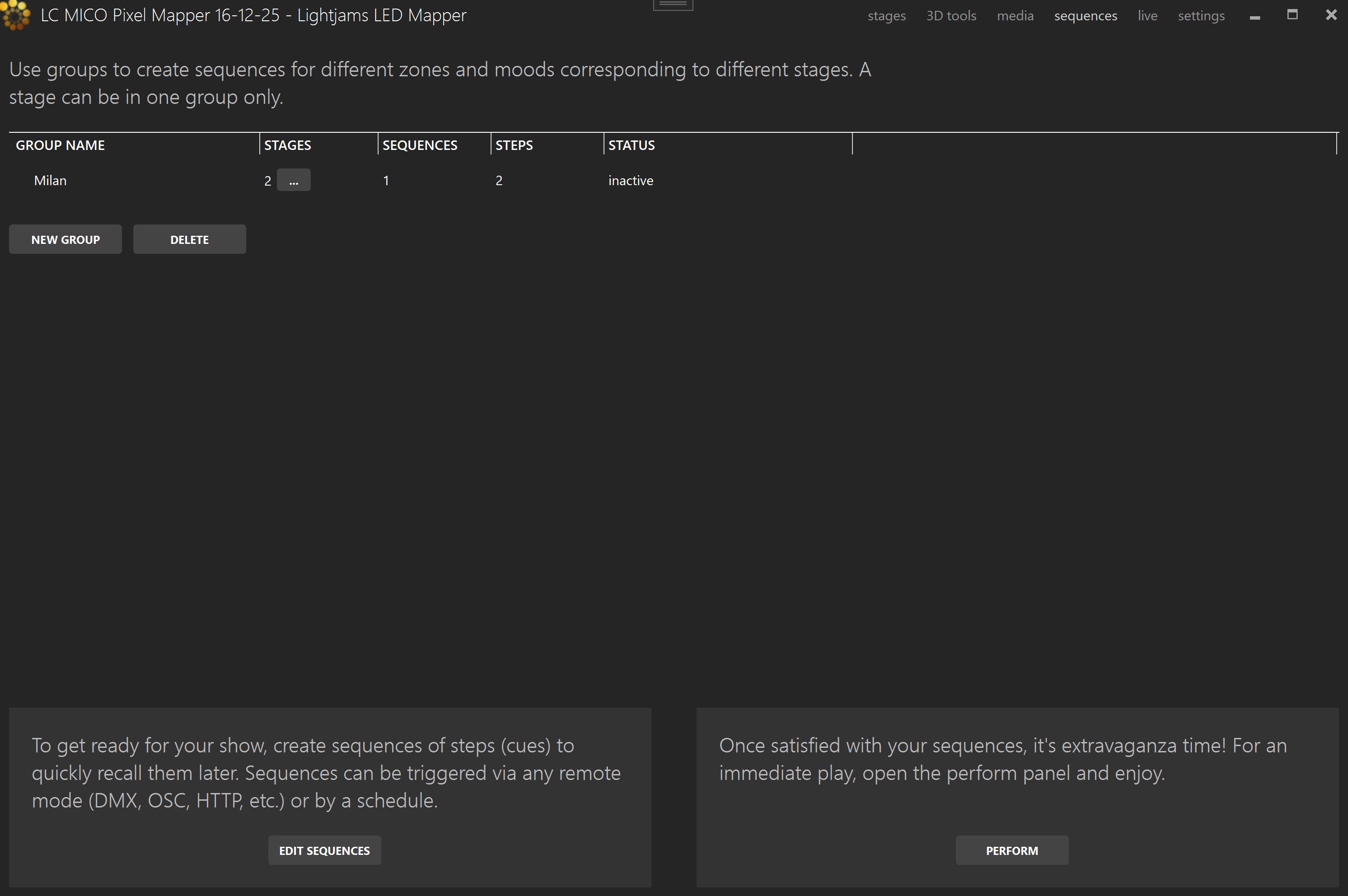
New group
Stage number button
Delete
Edit sequences (alt-E)
Perform (alt-P)
Groups
A group is a set of stages that you want to control together in the sequences system. Sequences, steps, scheduling, and the Perform panel all work at the group level.
What a group contains
Why groups are useful
How groups are used
One stage, one group
Independent playback per group
Think of a group as the playable unit of the Sequences section. You do not store cues for isolated strips or for the whole project at once; you store them for a chosen set of stages that should behave together.
Edit sequences
Go in Live Mode and configure the stages of the group as you want and then store the result as a step of a sequence. The settings for each stage that are stored in a step are: main media selection, media parameters, stage activation, stage speed, stage color filter, transition duration, transition effect and the whole state of the audio mix. An interpolation is made for transitions between steps and sequences for all numeric parameters, including the media parameters. For example, you can change the zoom level of an eye candy effect to animate it between steps.
Each group can have up to 255 sequences and each sequence can have as many steps (cues) as you want. You’ll then be able to recall these sequences during a live show or via any remote mode.
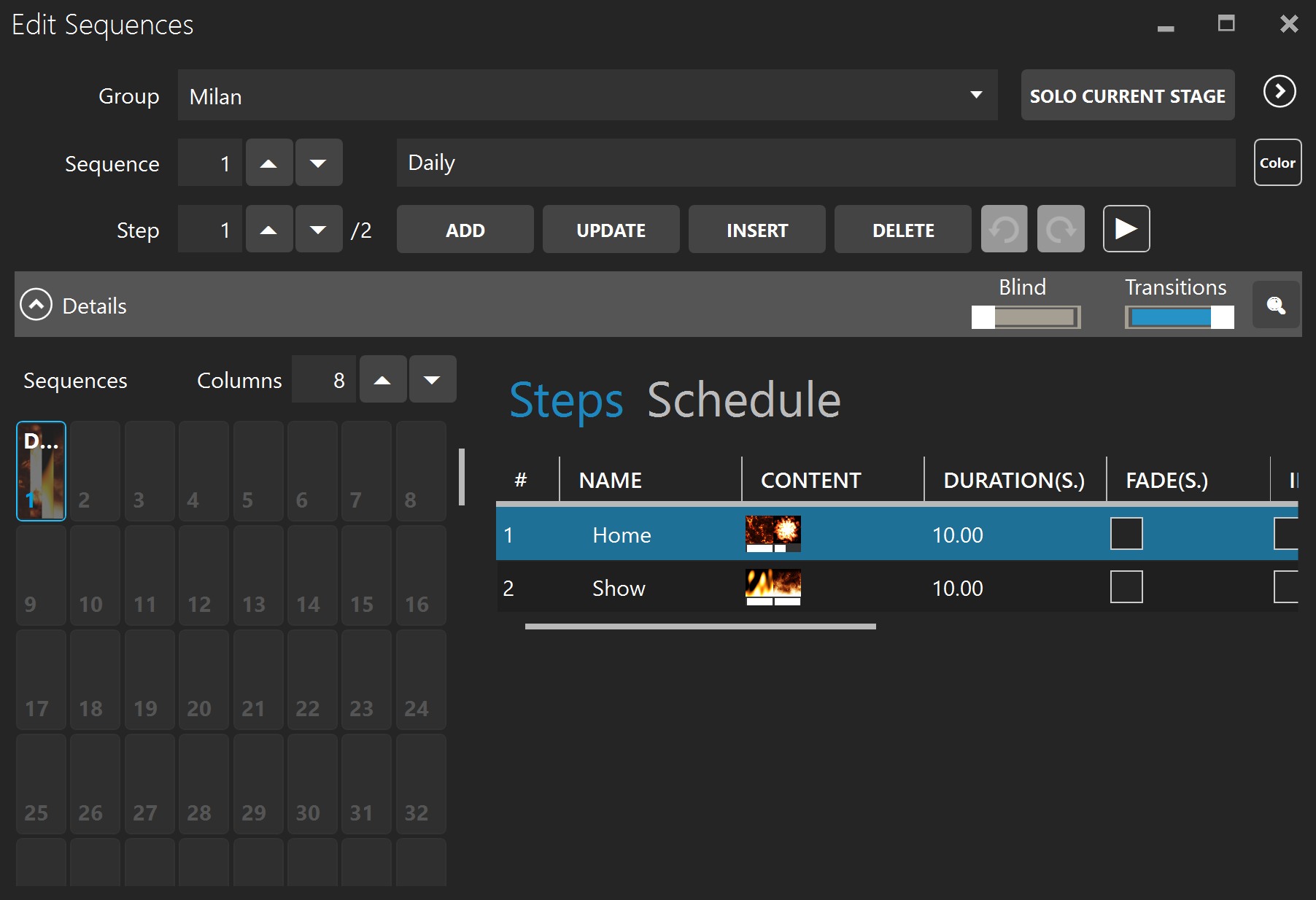
Overview section (upper part)
Group
Stage filters expander
Solo current stage
Sequence
Sequence color tag
Sequence name
Step
Sequence color tag
Add (ctrl-space-A)
Update (ctrl-space-U)
Insert (ctrl-space-I)
Delete (ctrl-space-D)
Undo/redo (ctrl-z, ctrl-y)
Auto play
The editor is designed to work together with Live Mode: build the look live, then store it with Add, Update, or Insert. The step shortcuts still work while your focus is outside the sequence window, which makes recording cues much faster.
Details section (bottom part)
Details expander
Blind
Transitions
Find sequences by media
Sequences
Columns
Steps tab
Step columns
Step context menu
Schedule
You can schedule the current sequence so that it starts automatically. A group has its own scheduler, allowing each group to play one sequence at a time.
Start time
Relative to
Duration
Loop
Start and end dates
Active days
Perform panel
The perform panel is a touchscreen, keyboard and MIDI controller friendly interface to control your show. You can trigger your sequences and play live with the intensity, speed, strobe, tap tempo and more. Most of the controls can also be controlled via HTTP and OSC.
Group
Active
Master intensity and speed
Shortcuts
Sequences
Go/back
Tap tempo
Tempo dividers (/1, /2, /4…)
Play button
Play mode (loop, all, row, …)
Performer shortcuts
The performer can be controlled by shortcuts so you can operate it from a computer keyboard, a MIDI controller, or an external OS2L source such as VirtualDJ. Shortcuts are mapped to performer actions like Go, Back, Tap Tempo, sequence selection, sequence play, performer active, intensity, speed, strobe, blackout, freeze, fade time, color controls, presets, and group selection.
How shortcuts work
Shortcuts editor
Save and load shortcut files
.sc.xml format. LJLM lets you save or load Keyboard only, MIDI only, OS2L only, or all shortcut types together.Keyboard shortcuts
MIDI shortcuts
OS2L shortcuts
Shortcut reassignment protection
OS2L in the performer
OS2L stands for Open Sound to Light. In LJLM, it is used as a network input to receive beat information and performer control messages from software such as VirtualDJ.
What OS2L can do
Tempo source
Direct sequence triggering
How to configure OS2L in LJLM
How to configure the sender
127.0.0.1:9666 when both applications run on the same computer.OS2L trigger types in LJLM
Live Mode
Shortcut key: alt-L
The main goal of the live mode is to see what’s playing on each stage and configure the effects. For example, if a playlist is running, you’ll see what’s happening in real-time, including the transitions. If nothing is controlling the stage, you’ll be able to manually select what’s playing.
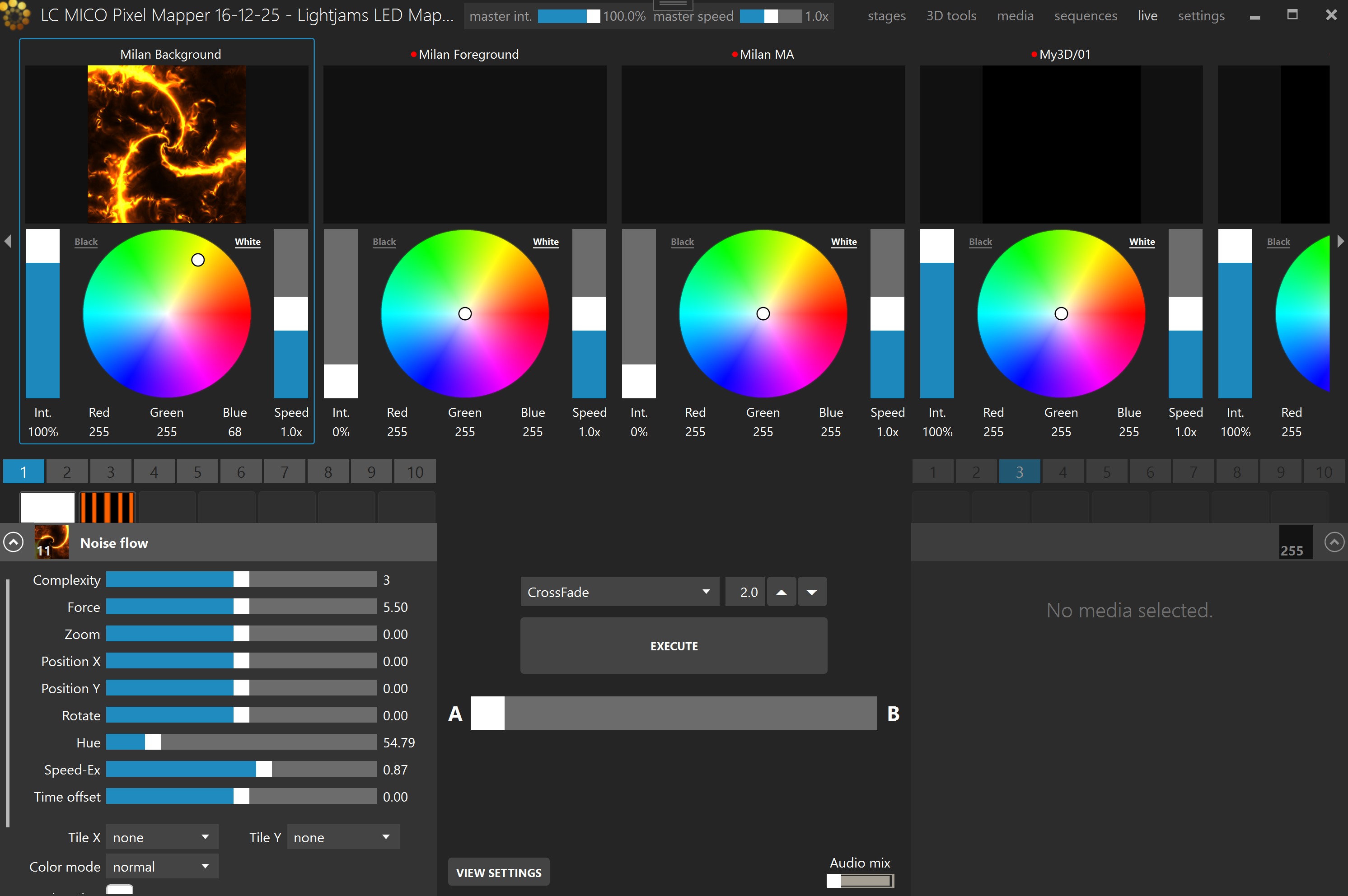
A and B media banks
A and B configuration panels
A-B Fader
Execute
Transition effect and duration
Intensity
Color wheel
Speed
Thumb size
Audio reactive mix
DVI
Master intensity and speed
You can use LJLM to output video to a projector or TV without controlling LEDs. Simply create a stage and don’t put any LEDs on it. Then in the live mode, click the DVI button.
Using black and white media allows you to use the color filter and get exactly the RGB color you want as output.
Use the live mode as a monitor to help you see what’s going on while remotely controlling LJLM with another lighting console. You can also open multiple DVI outputs (one per stage) and use them as monitors.
Settings
Shortcut key: alt-I
Project
This is the overall panel, displaying the most important info about your project status.
New project
Load (ctrl-o)
Save as
Save (ctrl-s)
Import
Export patch
Firewall
DMX universes
Stages
Strips
Mapped LEDs
Output rate (Hz)
DMX output
Lock stages
Run at startup
Language
A project backup file is created every 5 minutes. To avoid slowdown during a live show, you need to manually save the project to trigger the backup creation. To open a backup, select the Backup file type in the file browser when opening a project. To set the backup to be the current project, simply save the project.
The Import menu can also import DXF and SVG drawings, strips from supported LED controllers such as Advatek PixLite Mk3 and DMXKing LeDMX MAX, plus xLights xModels.
Import xLights/xModels
Use the Import menu under xLights to select one or multiple xModel files. Strips will be automatically created to best fit the models.
Import CSV LEDs
Select one or multiple CSV files to import. Each row of the CSV file represents one LED.
Create one bundle per file
The supported columns are:
X
Y
Protocol
Type
Universe
Address
Group
Sub-group
Strips are automatically created for consecutive LEDs with the same group and sub-group. All columns are optional.
A stage will be created to contain all LEDs based on their X and Y positions. To export the LEDs of a stage as a CSV, see Stage Tab.
Import DXF
Use the Import menu to load an AutoCAD 2000+ DXF file. LJLM shows the DXF layers and lets you choose which ones to import.
Layers
Views
Create one stage per layer
Explode polylines
LEDs per meter
Use DXF import when your installation geometry is already available as an AutoCAD drawing and you want LJLM to derive strips from the line work and layers.
Import SVG
Use the Import menu to load a Scalable Vector Graphics file and generate strips from its vector elements.
Create strips for text elements
SVG drawing pixels used to generate one LED
You can annotate SVG elements with optional attributes:
led-count
led-type
reversed
group
sub-group
dmx-protocol
universe
address
Attribute names can optionally start with data-. For example, data-led-count is equivalent to led-count.
A child element of type <desc> or <title> creates a note positioned over the element.
All SVG import names and values are case-insensitive.
Art-Net
Settings for the Art-Net universes.
Adapter
Universe display
Scan nodes
Locate uni.
Monitor
Optimize frames
ArtSync
Universe IP addresses
sACN
Settings for the sACN universes.
Adapter
First universe
Priority
Locate uni.
Monitor
Optimize frames
sACN Sync
Universe IP addresses
KiNet
Settings for the Philips Color Kinetics devices (power supplies). Both protocol versions are supported, which are KiNet v1 (DMXOUT) and KiNet v2 (PORTOUT). For KiNet v2, you map each KiNet device’s port to a universe in LJLM. You can map up to 8192 ports. Use Philips QuickPlay Pro to configure and get the IP addresses of your KiNet devices.
Adapter
Locate uni.
Monitor
Device IP addresses
Port
Scheduler
The scheduler is responsible to activate your sequences for those with scheduling options. The sunrise and sunset times are automatically updated throughout the year based on your location.
Stop during daylight
Scheduler active
Your position
Offsets (minutes)
Test helpers
Audio
Activate and configure up to 8 audio inputs. The audio inputs are used by the audio reactive effects and the audio reactive mix. Activate the loopback input to listen to what’s playing on this computer.
Activation switch
Volume
Falloff speed
Lower/higher frequencies (Hz)
Auto gain
Auto gain up delay
Up/down arrows
WaveIn/ASIO
MIDI
The detected MIDI controllers are listed here. Activate the ones you want to use for your performance. The configuration for which notes and CC messages to use is done in the Perform panel. Multiple controllers can be used at the same time as long as they are transmitting on different channels or at least sending different note or CC messages.
White Balance
Configure how the different LED types appear in the stage monitor. You can adjust their color temperature and intensity for a more accurate preview, which is particularly important when using LEDs with multiple types of whites such as WWA.
License
Manage your licenses. You can import multiple licenses to get more DMX universes.
Backup
Import
Hardware ID
Remote Control
LJLM can be remotely controlled in many ways. Multiple inputs can be active at the same time to give you even more flexibility. The DMX input always takes priority.
DMX – Art-Net, sAcn and Enttec USB Pro
Settings for remotely controlling LJLM with a lighting console.
Input mode
Network adapter
Universe
Monitor
Address
Stage fixture mode
DMX value mode
Percent: makes it easy for consoles working in percent.
Raw: makes it easy for consoles working in the 0-255 DMX range.
Stages
Media remote
The DMX sheet showing what can be controlled and by which channel is integrated in LJLM. It is dynamically generated based on the current remote settings and your stages. This way, you can’t lose it!
The groups created in the sequences panel are automatically added to the remote control.
When no DMX data is received for more than 5 seconds, the remote control mode will automatically be deactivated. This is a failsafe feature in case the remote console has a problem. When this happens, the schedule resumes right away. If there are no schedules, then the current media will continue to play.
Basic Fixture Mode (8 channels per stage)
| Channel | Name | Values | Note |
|---|---|---|---|
| 1 | Remote control mode |
0: Remote control deactivated 1-254: Reserved, don’t use 255: Remote control activated |
Remote control activated only when receiving 255. 0 disables the remote control mode and the stage goes back to being controlled via the schedule (if any) or manually. |
| 2 | Media index |
0: No function 1-99: Media index |
The media to play. If needed, a transition (crossfade) is automatically executed between the current media and the new one. This effectively controls the A and B sides in the live panel for you. |
| 3 | Intensity level |
0: Stage deactivated 1-255: Level |
The output level (dimmer). When at 0%, the stage is considered to be deactivated and doesn’t override stages with a lower precedence anymore - it becomes transparent. To keep the stage activated and force a black output, use the color filters at 0%. |
| 4 | Red filter | 0-255 | Filters the color output. |
| 5 | Green filter | 0-255 | Filters the color output. |
| 6 | Blue filter | 0-255 | Filters the color output. |
| 7 | Playback speed |
0: Paused 1-255: Speed up to 10x. 25 = 1x |
For some type of media like videos, effects and texts, the speed controls how fast the playback goes. For live streams, the speed has no effect. |
| 8 | Transition duration |
0: No transition 1-255: Duration up to 20 seconds. 12 = 1s. |
When transitioning between media, this controls the duration of the crossfade. |
Extended Fixture Mode (15 channels per stage)
| Channel | Name | Values | Note |
|---|---|---|---|
| 1 | Remote control mode |
0: Remote control deactivated 1-254: Reserved, don’t use 255: Remote control activated |
Remote control activated only when receiving 255. 0 disables the remote control mode and the stage goes back to being controlled via the schedule (if any) or manually. |
| 2 | Intensity level (MSB/coarse) |
0: Stage deactivated 1-65535: Level |
The output level (dimmer). When at 0%, the stage is considered to be deactivated and doesn’t override stages with a lower precedence anymore - it becomes transparent. To keep the stage activated and force a black output, use the color filters at 0%. |
| 3 | Intensity level (LSB/fine) | ||
| 4 | Red filter | 0-255 | Filters the color output. |
| 5 | Green filter | 0-255 | Filters the color output. |
| 6 | Blue filter | 0-255 | Filters the color output. |
| 7 | Media A speed |
0: Paused 1-255: Speed up to 10x. 25 = 1x |
For some type of media like videos, effects and texts, the speed controls how fast the playback goes. For live streams, the speed has no effect. |
| 8 | Media B speed |
0: Paused 1-255: Speed up to 10x. 25 = 1x |
For some type of media like videos, effects and texts, the speed controls how fast the playback goes. For live streams, the speed has no effect. |
| 9 | Media A index |
0: Empty 1-99: Media index |
The media to play on side A. |
| 10 | Media B index |
0: Empty 1-99: Media index |
The media to play on side B. |
| 11 | Media mixing position (MSB/coarse) |
0-65535 0: media A fully active 65535: media B fully active |
Controls the position of the mixing effect, from A to B. |
| 12 | Media mixing position (LSB/fine) | ||
| 13 | Mixing position modifier |
0: No function 1-255: Various mapping functions |
Spices up the mixing position by applying a function like bounce, sigmoid and exponential. See the list of functions in LJLM. |
| 14 | Mixing effect |
0: no effect 1: crossfade 2: black fade 3: white fade 4-255: Various effects |
Determines the effect to be applied when mixing the A and B sides. From simple crossfade to complex effects including rotations, scaling and translations. See the list of effects in LJLM. When not needed, select the ‘no effect’ to avoid wasting CPU. |
| 15 | Reserved (unused) |
Extended2 Fixture Mode (23 channels per stage)
| Channel | Name | Values | Note |
|---|---|---|---|
| 1 | Remote control mode | 0: Remote control deactivated 1-254: Reserved, don’t use 255: Remote control activated |
Remote control activated only when receiving 255. |
| 2-3 | Intensity level | 16-bit level | Controls the media intensity of the stage. |
| 4-9 | Red, Green, Blue filters | 16-bit RGB | High precision color filter control. |
| 10 | Media A speed | 0: paused, 25 = 1x, 255 ≈ 10x | Playback speed for media A when applicable. |
| 11 | Media B speed | 0: paused, 25 = 1x, 255 ≈ 10x | Playback speed for media B when applicable. |
| 12 | Transition duration | 0: no transition, 1-255 up to 20 seconds | Used when the AUTO media index takes over the A-B sides. |
| 13-14 | Media AUTO index | 0: use media A-B index | When not 0, plays a media and automatically controls the A-B sides for you. |
| 15-16 | Media A index | 16-bit media index | Selects the media on side A. |
| 17-18 | Media B index | 16-bit media index | Selects the media on side B. |
| 19-20 | A-B media mixing position | 0-65535 | Controls the mix position from media A to media B. |
| 21 | Mixing position modifier | Indexed mapping functions | Maps the mixing position to functions such as bounce or sigmoid. |
| 22 | Mixing effect | Indexed list of effects | Selects the media mixing effect. |
| 23 | Merge mode | Indexed list of merge modes | Changes the merge mode of the stage. |
Group (12 channels per group)
| Channel | Name | Values | Note |
|---|---|---|---|
| 1 | Group active and remote control enabled |
0-245: Remote control deactivated 246-250: Group inactive 251-255: Group active |
Controls the group active switch. When remote control is deactivated, the scheduler can take over. Deactivating the group deactivates all stages in the group. |
| 2 | Intensity level (MSB/coarse) | 0-65535: Level | Multiplies the intensity of all stages in the group. 0 does a blackout without deactivating the stages (they continue playing). |
| 3 | Intensity level (LSB/fine) | ||
| 4 | Red filter | 0-255 | Filters the color output. |
| 5 | Green filter | 0-255 | Filters the color output. |
| 6 | Blue filter | 0-255 | Filters the color output. |
| 7 | Speed |
0: Paused 1-255: Speed up to 10x. 25 = 1x |
Multiplies the speed of all stages of the group. |
| 8 | Sequence number |
0: Stop 1-255: Sequence number |
0 stops the playback but doesn’t blackout the stages as long as the group is active. |
| 9 | Step number |
0: Auto 1-255: Step number |
0 automatically plays all the steps using the programmed duration of each step. For step numbers, it wraps around the number of steps automatically. So if the sequence has 4 steps and you specify step 5, then step 1 will play. This is to avoid needing to know the exact number of steps. |
| 10 | Transition time overridden |
0-250: no 251-255: overridden |
Whether the transition time between steps and sequences is using the programmed time or the time of channel 11. |
| 11 | Transition time |
0: No transition 1-255: Duration up to 20 seconds. 12 = 1s. |
The time of the transition between steps and sequences. |
| 12 | Strobe |
0: off 1-255: strobe on, slow-fast |
Strobes the intensity of the group. |
CITP/MSEX
Activate this option to enable LJLM to communicate with other CITP/MSEX compatible consoles and software. CITP/MSEX version 1.0, 1.1 and 1.2 are available. The things LJLM can do are:
-
Send the media thumbnails to your console
-
Stream the LED preview of every stage to your console or visualizer
-
Send the stage statuses, including the current playing media
OSC
Settings for remotely controlling LJLM via OSC (Open Sound Control) over the network. LJLM listens for incoming OSC on all network adapters.
Stage addresses
| Address | Description |
|---|---|
/ljlm/stages/{stage name}/live/intensity |
0..1 |
/ljlm/stages/{stage name}/live/rgb or /r, /g, /b |
0..1, 0..1, 0..1 |
/ljlm/stages/{stage name}/live/media |
0..999 |
/ljlm/stages/{stage name}/live/speed |
0..10 |
/ljlm/stages/{stage name}/live/transitionFx |
0..43 |
/ljlm/stages/{stage name}/live/transitionDuration |
0..9999 seconds |
/ljlm/stages/{stage name}/live/audioMixControlled |
{0: no, 1: yes} |
/ljlm/stages/{stage name}/live/remotelyControlled |
{0: no, 1: yes} |
/ljlm/stages/{stage name}/live/mix/position |
0..1 |
/ljlm/stages/{stage name}/live/mix/A/media |
0..999 |
/ljlm/stages/{stage name}/live/mix/A/speed |
0..10 |
/ljlm/stages/{stage name}/live/mix/B/media |
0..999 |
/ljlm/stages/{stage name}/live/mix/B/speed |
0..10 |
/ljlm/stages/{stage name}/merge |
1..12 or merge mode name |
Group addresses
| Address | Description |
|---|---|
/ljlm/groups/{group name}/performer/active |
{0: no, 1: yes} |
/ljlm/groups/{group name}/performer/paramTransitionDuration |
0..9999 seconds |
/ljlm/groups/{group name}/performer/intensity |
0..1 |
/ljlm/groups/{group name}/performer/blackout |
{0: no, 1: yes} |
/ljlm/groups/{group name}/performer/bumpingIntensity |
{0: no, 1: yes} |
/ljlm/groups/{group name}/performer/strobing |
{0: no, 1: yes} |
/ljlm/groups/{group name}/performer/strobeOnDuration |
0..1 seconds |
/ljlm/groups/{group name}/performer/rgb or /r, /g, /b |
0..1, 0..1, 0..1 |
/ljlm/groups/{group name}/performer/speed |
0..10 |
/ljlm/groups/{group name}/performer/freeze |
{0: no, 1: yes} |
/ljlm/groups/{group name}/performer/bumpingSpeed |
{0: no, 1: yes} |
/ljlm/groups/{group name}/performer/tempoBPM |
0..300 |
/ljlm/groups/{group name}/performer/tap |
Press the tap tempo button. |
/ljlm/groups/{group name}/performer/cleartempo |
Deactivate the tap tempo. |
/ljlm/groups/{group name}/performer/tempoDivider |
1..128 |
/ljlm/groups/{group name}/performer/autoGo |
{0: no, 1: yes} |
/ljlm/groups/{group name}/performer/playMode |
{0: loop, 1: row, 2: column, ...} |
/ljlm/groups/{group name}/performer/play |
sequenceId, [stepId] |
/ljlm/groups/{group name}/performer/go |
Play the next step. |
/ljlm/groups/{group name}/performer/back |
Play the previous step. |
/ljlm/groups/{group name}/sequences/{sequenceId}/schedule/enabled |
{0: no, 1: yes} |
Media and settings addresses
| Address | Description |
|---|---|
/ljlm/media/slots/{slotId}/parameters/{name} |
Range as in the live panel. |
/ljlm/media/slots/{slotId}/parameters/{name}/normalized |
0..1 |
/ljlm/settings/masterIntensity |
0..1 |
/ljlm/settings/masterSpeed |
0..2 |
/ljlm/settings/dmxOutputActive |
{0: no, 1: yes} |
/ljlm/settings/schedulerActive |
{0: no, 1: yes} |
Addresses and names are case-insensitive.
Media index 0 is an empty slot.
RGB values can be sent as a single
/rgbmessage or separately through/r,/gand/b.
audioMixControlledcontrols the audio mix activation.
remotelyControlleddetermines whether OSC overrides the scheduler.Use
*as a wildcard in the stage name to target multiple stages at once.
HTTP
Settings for remotely controlling LJLM via HTTP, which is a protocol based on TCP/IP. This is the most reliable way to integrate LJLM with control systems like Crestron and Pharos or to create custom web interfaces. LJLM listens for incoming HTTP requests on all network adapters.
General endpoints
| Request | Description |
|---|---|
GET /ljlm/status |
Returns the status of all sub-systems, like in the Settings > Project page. |
GET /ljlm/heartbeat |
Returns 200 OK if the server is running. |
GET /ljlm/settings |
Returns global settings such as master intensity, master speed and scheduler state. |
POST /ljlm/settings |
Sets global settings such as masterIntensity 0..1, masterSpeed 0..2, and similar values. |
Stage endpoints
| Request | Description |
|---|---|
GET /ljlm/stages |
Returns the list of stages. Use includeState 0 for names only or 1 for ids and additional info. |
GET /ljlm/stages/{stage name or id} |
Returns the state of a stage with its id, merge mode and other info. |
POST /ljlm/stages/{stage name or id} |
Updates stage-level properties such as merge {name}. |
GET /ljlm/stages/{stage name or id}/live |
Returns the live state of the requested stage. |
POST /ljlm/stages/{stage name or id}/live |
Controls the stage live parameters: intensity 0..1, media 0..999, speed 0..10, transitionFx {name}, transitionDuration 0..9999, red 0..255, green 0..255, blue 0..255, audioMixControlled 0 or 1, and remotelyControlled 0 or 1. |
POST /ljlm/stages/{stage name or id}/live/dvi |
Shows or hides existing DVI windows with visible 0 or 1. |
GET /ljlm/stages/{stage name or id}/patch |
Returns the list of all patched strips for that stage. |
GET /ljlm/stages/{stage name or id}/monitor |
Returns an MJPEG stream of the LED preview. Parameters: width, height, fps. |
GET /ljlm/stages/transitionFxNames |
Returns the list of valid transition effect names. |
GET /ljlm/stages/mergeNames |
Returns the list of valid merge mode names. |
Group endpoints
| Request | Description |
|---|---|
GET /ljlm/groups |
Returns the list of groups. |
GET /ljlm/groups/{group name or id}/stages |
Returns the list of stages in the group. |
GET /ljlm/groups/{group name or id}/sequences |
Returns the list of sequences in the group. |
GET /ljlm/groups/{group name or id}/sequences/{sequenceId} |
Returns information about the sequence. |
POST /ljlm/groups/{group name or id}/sequences/{sequenceId}/schedule |
Enables or disables the schedule with enabled 0 or 1. |
GET /ljlm/groups/{group name or id}/performer |
Returns the full state of the performer. |
POST /ljlm/groups/{group name or id}/performer |
Sets performer values. Any returned performer parameter can be set except computed parameters. |
POST /ljlm/groups/{group name or id}/performer/go |
Plays the next step in the sequence. |
POST /ljlm/groups/{group name or id}/performer/back |
Plays the previous step in the sequence. |
POST /ljlm/groups/{group name or id}/performer/tap |
Presses the tap tempo button. |
Media endpoints
| Request | Description |
|---|---|
GET /ljlm/media/slots |
Returns the list of filled media slot ids. Use includeState 0 for ids only or 1 for full slot states. |
GET /ljlm/media/slots/{id} |
Returns the state of a media slot. |
GET /ljlm/media/slots/{id}/thumbnail |
Returns the thumbnail as a PNG. Parameters: width, height. |
GET /ljlm/media/slots/{id}/monitor |
Returns an MJPEG stream of the media. Parameters: width, height, fps. |
POST /ljlm/media/slots/{id} |
Loads media into the slot. Parameters: path for an existing local file, or multipart form file upload for a new media file. |
GET /ljlm/media/slots/{id}/parameters |
Returns the list of all parameters of the media. |
POST /ljlm/media/slots/{id}/parameters/{name} |
Changes a parameter value using value in the same range as in the live panel. |
POST /ljlm/media/slots/{id}/parameters/text |
Changes the text of a text media using the value parameter. |
For example, to start sequence 1 of the group background:
POST /ljlm/groups/background/performer?active=1&sequenceId=1
To get the performer state of the group background:
GET /ljlm/groups/background/performer
All data is returned in JSON.
Use the returned HTTP status code for error handling.
Addresses and names are case-insensitive.
Parameters can be provided in the query string or form data.
Media id 0 is an empty slot.
Use
*as a wildcard in the stage name to target multiple stages at once for POST requests.
The base URL to access the API is: http://YOUR-COMPUTER-NAME:port/ljlm. If you prefer, you can replace the computer name by its IP address or localhost if the server is running on the same computer. The port can be omitted if it is 80, which is the default for HTTP.
You can restrict the access to the API by activating the Basic Auth feature. For more details see https://en.wikipedia.org/wiki/Basic_access_authentication.
How-to Guides
This section gives you practical step-by-step workflows for the most common LJLM tasks. Follow them in order when you are learning the software or when you want a reliable checklist during setup.
How to create a first mapped stage from scratch
This how-to takes you from an empty project to a first working stage with visible output.
What you will achieve
Before you start
Create or open a project. Go to Settings > Project and save the project early so media paths and backups are easier to manage.
Create a stage from the Home Screen or the Stages Manager. Give it a clear name based on the real installation area, then choose a width and height matching the aspect ratio of the media you expect to play.
If you already have a reference image of the installation, set it as the stage background. This makes strip placement much easier and helps keep the mapping aligned with the physical installation.
Open the Add Strips Dialog. Enter the number of strips or fixtures, the number of LEDs per strip, and the correct LED type. Choose the appropriate DMX protocol such as Art-Net, sACN or KiNet.
Set the starting universe and starting address. If you are creating an array or other regular shape, make sure the patching direction matches the real wiring direction of the installation.
Place the strips on the stage. Use the edit zone to move, resize, rotate, and align them until the stage visually matches the real layout. Use the grid and snapping features if you need more precision.
Go to the Testing Tab and activate a test pattern. Move the testing rectangle over the stage to confirm that LEDs light up where you expect.
Open the Media Library and load a media item such as a built-in effect, image or video. Built-in effects are recommended for a first test because they work immediately and do not depend on external files.
Go to Live Mode. Select the media for the stage, raise the stage intensity, and make sure the stage is active. If the stage output is black, check the color filter and make sure intensity is not at 0.
Open the stage monitor if needed. This lets you verify whether the mapping itself is correct even before checking the real fixtures.
What to check if it does not work
The stage must be active and its intensity must be above 0.
The DMX output must be enabled under Settings > Project.
The selected network adapter must match the physical network used by the controller.
The controller must be configured for the same protocol as the strips in LJLM.
The universes and addresses in LJLM must match the controller configuration.
If the stage monitor looks correct but the fixtures do not react, the issue is usually in the patch, controller, network, or fixture configuration.
For a first LJLM test, use one simple stage, a built-in effect from the Media Library, and the Testing Tab. This lets you confirm the mapping and the output before you start building extra stages, sequences, or layered looks.
Related sections: Home Screen, New Stage Dialog, Add Strips Dialog, Testing Tab, Media Library, Live Mode, Project, Art-Net, sACN, KiNet.
How to patch an LED strip or matrix correctly
This how-to helps you match the software patch to the real wiring of your strips or fixtures so the visual content flows in the right order.
What you will achieve
Before you start
Open the Add Strips Dialog. Enter the number of strips or fixtures and the correct LED count per strip. If you are patching a matrix, use multiple strips arranged as lines.
Select the correct LED type. This must match the real fixture channel order and feature set, for example RGB, RGBW, RGBA, White, WWA, or a 16-bit variant when needed.
Select the correct DMX protocol. Use the same protocol that the controller is expecting: Art-Net, sACN or KiNet. If you are not ready to output yet, you can temporarily leave strips unpatched and patch later.
Set the starting universe and starting address. LJLM will continue patching from there. If you need gaps between LEDs or fixtures, use the LED address offset.
For arrays and repeated layouts, choose the correct patching direction. This is critical. The patching direction tells LJLM how to number the LEDs so the content follows the same path as the physical wiring.
If the installation is a snake-wired matrix, choose the patching direction that matches the alternating wiring of the rows or columns. This avoids manually reversing every other strip later.
If the controller requires universes to break before they are full, set Break universe after accordingly. Otherwise, leave it at the default behavior so LJLM fills the universe naturally.
After patching, go to the Testing Tab. Use a small testing rectangle and move it slowly across the stage. Watch the real LEDs to confirm that the lit LEDs move in the same direction as the rectangle.
If the content direction is wrong, correct the strip orientation. Depending on the situation, you may need to reverse the LEDs, flip the geometry, or choose a different patching direction.
If the order is correct but specific strips appear out of sequence, review the universe and address ranges of those strips in the Strip List or Edit Strips Dialog.
How to verify a matrix quickly
Test left-to-right movement.
Test top-to-bottom movement.
Use Test 1st LEDs only to identify where each strip starts.
If using snake wiring, use strip selection tools such as select odd or even strips when you need to adjust alternating rows.
What to check if it does not work
The controller may be configured for the wrong LED protocol even if the DMX patch is correct.
The strips may be using the wrong universe or address range.
The patching direction may be reversed.
The LED count per strip may be wrong.
The controller may expect another port, universe numbering mode, or fixture personality.
LJLM is designed to patch many strips quickly, especially arrays and matrices. After the bulk patch is created, use the Testing Tab, Test 1st LEDs only, and the Strip List selection tools to verify that the patching direction and the strip order are correct.
Related sections: Add Strips Dialog, Edit Zone, Strip List, Edit Strips Dialog, Testing Tab, Art-Net, sACN, KiNet.
How to fix wrong colors, wrong pixel order, or wrong white behavior
This how-to is for installations where the output is active but the displayed colors are wrong, swapped, dim, or use the wrong white channel behavior.
What you will achieve
Before you start
Go to the Testing Tab and enable a test pattern. Set the test color to pure red.
Observe the real fixture output. If the LEDs show green or blue instead of red, the pixel type or component order is wrong.
Repeat the test with pure green and pure blue. Write down the actual observed order. For example, if red shows as blue, green shows as red, and blue shows as green, the strip behaves like a BRG or similar order rather than RGB.
Open the Edit Strips Dialog for the affected strips and change the LED type to the correct component order.
Test the three primary colors again. Continue until red, green and blue all display correctly.
If you are working with fixtures that include a white or amber channel, verify that you selected the correct LED type family. For example, use RGBW for red, green, blue and white fixtures, RGBA for red, green, blue and amber fixtures, and WWA or related white types when multiple white channels are used.
If the real fixture has separate white channels and the preview or output does not behave naturally, review the selected white-oriented LED type such as WhiteCool, WhiteNeutral, WhiteWarm or WWA. These types are designed to give a more accurate preview and channel behavior.
If the fixture supports high precision colors and the transitions look coarse, consider enabling the 16-bit option or using a 16-bit compatible type where appropriate.
If the colors are correct in LJLM’s monitor but wrong on the real fixture, check the controller configuration as well. Some LED controllers can be set to the wrong pixel protocol or color order independently from LJLM.
Once the output is correct, save the project immediately so the working strip type and settings are preserved.
Common symptoms and likely causes
Red, green and blue are swapped
White looks tinted or weak
The stage monitor looks right but the fixture looks wrong
Color transitions look stepped
What to check if it still does not work
Confirm the controller is set to the correct physical LED protocol such as WS2811, WS2812 or another compatible protocol.
Confirm the fixture is not in another personality or color mode.
Confirm that the same strips were updated across all reused stages if the installation uses shared strips in multiple stages.
If only part of the installation is wrong, compare the strip settings of a working strip with a failing one in the Strip List and Edit Strips Dialog.
Use the Testing Tab to run pure red, green, blue, and white tests before troubleshooting media. In LJLM, wrong colors are usually fixed by selecting the proper LED type and component order in the strip dialogs, and by using the right white-oriented type when the fixture has dedicated white channels.
Related sections: Testing Tab, Add Strips Dialog, Pixel Types, Edit Strips Dialog, White Balance, Troubleshooting.
How to merge multiple stages to create more complex effects
This how-to shows how to layer three stages with different merge modes so you can build a richer result than any single stage could produce on its own.
What you will achieve
Before you start
Create or choose three stages that use the same mapped strips. Name them clearly, for example Background, Mask, and Highlight. Put them in a known order in the Stages Manager.
Set the first stage, Background, to Overwrite merge mode. Load broad content on it, such as a full-screen video, a gradient, or a slow-moving built-in effect. This stage becomes the base image for the LEDs under everything else.
Set the second stage, Mask, to Multiply merge mode. Load content that has useful brightness structure, such as stripes, soft blobs, or a black-and-white effect. In Multiply mode, darker values reduce the visibility of the stage under it, so this stage behaves like a video mask over the Background stage.
Set the third stage, Highlight, to Screen merge mode. Load bright content such as sparkles, white flashes, or a high-contrast effect. Screen mode tends to brighten the result, so this stage is useful for adding glow, shine, and visual energy on top of the already merged stages below.
Activate all three stages and assign media to each one in Live Mode. Make sure each stage intensity is above 0, otherwise that stage will not contribute to the merge.
Verify the stage order in the Stages Manager. LJLM merges stages from top to bottom in that list. The result of the first stage is combined with the second stage using the second stage’s merge mode, then that intermediate result is combined with the third stage using the third stage’s merge mode.
-
Observe the result and think of it in three passes:
Pass 1: the Background stage writes the initial image because it is set to Overwrite.
Pass 2: the Mask stage multiplies that image, so black areas hide the background, gray areas dim it, and white areas keep it visible.
Pass 3: the Highlight stage screens over the result, making bright parts even brighter and lifting the final image where the highlight content is active.
Adjust the media choice and stage intensity of each stage to shape the final look. If the merged image becomes too dark, reduce the influence of the Multiply stage. If it becomes too washed out, reduce the Screen stage or use more selective highlight content.
Try replacing one of the merge modes to understand the difference. For example, change the Highlight stage from Screen to Add for a more aggressive brightening effect, or change the Mask stage from Multiply to Overlay for a contrast-based interaction instead of a straightforward mask.
Once the blend is useful, save the project and consider duplicating the setup for alternate looks. The same mapped strips can support many different layered visual strategies.
How the result is computed and what it means
Overwrite base stage
Multiply stage
Screen stage
What to check if the merge does not behave as expected
The stages must overlap the same strips, otherwise there is nothing to merge on those LEDs.
The stage order in the Stages Manager matters. Reordering stages changes the final result.
A stage with intensity 0 or no active media becomes effectively transparent and will not influence the merge.
If a Multiply stage is too dark, most of the background may disappear. If a Screen or Add stage is too bright, detail may be lost.
If the result is confusing, test each stage alone first, then enable the next stage one by one.
In LJLM, stages are merged from top to bottom in the Stages Manager, and a stage only participates in the merge when it is activated. This makes it practical to keep one stage for the base content, one for shaping or masking, and one for highlights or accents.
Related sections: Stage Merging and Layering, Stages Manager, Live Mode, New Stage Dialog, Testing Tab.
How to create a playable show with sequences and schedules
This how-to gives you a concrete workflow for programming a small daily show that automatically starts, loops, and stops at the right time.
What you will achieve
Before you start
Open Sequences and create a group, for example Main Show. Add the stages that should play together in this show. If one stage should also be used elsewhere, duplicate it first because a stage can belong to only one group.
Go to Live Mode and build your first look. For example, set a background stage to a slow video, set a logo stage to a still image, and set a highlight stage to a built-in effect at low intensity.
Open Edit sequences and make sure the correct group is selected. Store that first look as step 1 using Add. Immediately give the sequence a clear name such as Opening Loop.
-
Return to Live Mode, change the stage configuration for the next look, and store that as step 2. Repeat until you have a small show, for example:
Step 1: calm opening look
Step 2: brighter full-installation moment
Step 3: logo emphasis or zone accent
Step 4: return to background loop
Use Update whenever a stored step is close but not right yet. Use Insert when you need to add a cue between two existing steps without rebuilding the whole sequence. Use the store filter if only some stages should be captured in the step.
Set or review the transition times between looks. Then test the sequence in the editor by selecting each step and confirming that the visual jump or fade feels right.
Open the Perform panel. Trigger the sequence, use Go and Back, and confirm that an operator can run the show manually if needed.
Now schedule the show. In the Schedule area for that sequence, set a start time, choose whether it is absolute or relative, set the duration, select the active days, and choose whether the sequence should loop during that scheduled window.
Open Scheduler and make sure scheduler activity, location, and daylight behavior are correct. If the installation should only run at night, configure sunrise and sunset behavior now.
Run a realistic test. Use the scheduler test helpers to simulate the target time, confirm that the group becomes active, the correct sequence starts, the loop behaves correctly, and the show stops when expected.
How this works for the end user
Live Mode is where you design each visual state.
Edit sequences is where you store those states as cues and organize them.
Perform panel is where an operator plays them manually.
Schedule and Scheduler are what make the same show run automatically without an operator.
What to check if the show does not play as expected
The group may be inactive in the Perform panel.
The scheduler may be temporarily disabled in Scheduler.
The stored step may not include the stage or parameter you expected because of the store filter settings.
The sequence may be correct, but the play mode may not be what you intended.
The wrong group may be selected when testing.
In LJLM, sequences are mainly a practical way to store looks as cues and recall them quickly. Build the looks in Live Mode, store them in Edit sequences, then use the Perform panel for manual recall or the optional Schedule features when the project needs automatic playback.
Related sections: Sequences, Edit sequences, Perform panel, Live Mode, Schedule, Scheduler.
How to build helper stages, zones, and alternate mappings
This how-to shows how to reuse one physical mapping to create zone stages, content-helper stages, and alternate layouts without repatching the installation from scratch.
What you will achieve
Before you start
Create and verify the main overall stage first. This stage should represent the whole installation and should already be tested in Testing Tab.
In the Strip List, select the strips that belong to one logical area, for example a logo, a doorway, a column group, or an outer border.
Right-click and use New stages from strips. If you want one controllable zone, use the option that copies all selected strips into one new stage. If you want one stage per strip, use one of the one-stage-per-strip options.
-
Choose the variant that matches your goal:
Use All strips in a new stage (copy) to create a real zone stage.
Use All strips on one line when you want a helper stage that makes content easier to create across the full LED count.
Use Each strip on a new line when you want matrix-like content preparation.
Use Each strip collapsed on a new point when you want to control each strip as if it were one pixel. This is very useful when each physical strip should behave like one grouped fixture rather than display detailed content along its full length.
Use keep positions when the new stage should preserve the spatial layout of the original stage.
Rename the new stages immediately so their purpose is clear, for example Logo Zone, Facade Helper Lines, or Border Mapping.
Open the new stage and inspect the geometry. Helper stages often benefit from a simpler arrangement than the real installation, while zone stages usually need to preserve the real layout.
Test the new stage in Live Mode with simple media. Confirm that it controls the intended LEDs and that the mapping style matches your creative goal.
Repeat the process for every important area of the installation. Over time you can build a small library of practical stages from the same physical strips.
Why this is valuable
Zone stages let you target specific physical areas quickly.
Helper stages make content creation easier than working on a complex real-world shape.
Collapsed-point stages let you treat each strip like one controllable grouped pixel, which is ideal for large installations where strip-level motion matters more than per-LED detail.
Alternate stages let the same installation behave differently for different moments of the show.
The New stages from strips commands are one of the most useful ways to reuse a mapping in LJLM. A copied zone stage, a one-line helper stage, or an Each strip collapsed on a new point stage can all target the same physical strips in different and very practical ways.
Related sections: Strip List, New stages from strips, Edit Zone, Stage Merging and Layering, Live Mode.
How to perform live with media, transitions, and audio-reactive mix
This how-to explains a practical operator workflow for using LJLM live during an event instead of only as a scheduled playback system.
What you will achieve
Before you start
Open Live Mode and choose the stage or stages you will control.
Use the A and B media banks to preload two candidate looks. Keep one side as the current live look and use the other side to prepare the next look.
Use the A-B fader for manual blends when you want full control over timing. Use Execute when you want LJLM to automatically run a transition from the more active side to the prepared side.
Choose the transition effect and duration based on the moment. Use simple crossfades for clean scene changes and more stylized transition effects only when they support the content instead of distracting from it.
Use stage intensity to bring zones in and out without changing the selected media. This is especially useful when you want a zone to fade up over an existing background stage.
Use the color wheel as a live color filter when the media itself is neutral enough to support recoloring. Black-and-white content often gives the most flexible results here.
Use stage speed carefully. Some effects and videos become much stronger when sped up slightly, but many become unreadable if pushed too far.
If the event is music-driven, enable audio-reactive mix and select the correct audio input. Test it before the show so you know how strongly it reacts and whether it suits the current media.
Keep a safe fallback look prepared in one media bank. When the performance gets busy, a known fallback lets you recover immediately.
If you are also using sequences, treat them as prepared moments and Live Mode as your override layer for live intervention.
Operator tips
Prepare media on the inactive side before transitioning.
Use intensity and color before changing content if you only need a subtle variation.
Reserve the most aggressive transition effects for occasional emphasis.
Keep one calm, reliable look ready at all times.
In LJLM live operation, it is usually cleaner to prepare the next look on the inactive A/B side, then transition with the fader or Execute. This works especially well when you combine prepared media slots with stage intensity, color filtering, and the audio reactive mix.
Related sections: Live Mode, Media Library, Perform panel, Stage Merging and Layering, Audio.
How to troubleshoot when the lights do nothing
This how-to gives you a strict troubleshooting order for the most stressful situation: the project seems fine, but the fixtures stay dark.
What you will achieve
Before you start
Check the obvious first in Live Mode: the stage must be active, intensity must be above 0, and a media item must actually be selected.
Open the stage monitor. If the stage monitor is black, the problem is inside LJLM configuration or media selection. If the stage monitor looks correct, the problem is more likely in the output, controller, or fixture chain.
Go to Project and verify that DMX output is enabled.
Go to the relevant protocol section such as Art-Net, sACN, or KiNet and confirm the correct network adapter is selected.
Verify the controller is configured for the same protocol and expected universe numbering as LJLM.
Use the Testing Tab and generate a simple bright test. This removes media complexity from the problem and tells you whether raw output is reaching the LEDs.
Check the strip patch. Open the Strip List or Edit Strips Dialog and verify protocol, universe, address, and pixel type for the affected strips.
If available for your protocol, use locate or monitor tools under the protocol settings to confirm that LJLM is actually sending data.
If LJLM is sending data but the fixtures still do nothing, verify the controller output ports, fixture mode, and LED protocol on the hardware side.
Reduce the system to one strip, one universe, one simple test, and one controller output. Once one small path works, scale back up gradually.
Fast diagnosis rule
Monitor black
Monitor correct, fixtures dark
What to avoid
Do not change protocol, adapter, universe, and pixel type all at once.
Do not troubleshoot using a complex show file first. Start with one stage and one test pattern.
Do not assume the controller and LJLM use the same universe numbering convention unless you checked it.
When LJLM outputs nothing, use the simplest built-in checks first: confirm the stage in Live Mode, confirm the stage monitor, then use the Testing Tab and the protocol monitor or locate tools. This separates a stage or media problem from a patch, network, or controller problem very quickly.
Related sections: Testing Tab, Project, Art-Net, sACN, KiNet, Edit Strips Dialog, Troubleshooting.
Troubleshooting
Output - Art-Net/sACN/KiNet
| Problem | Possible causes | Solutions |
|---|---|---|
| No Art-Net nodes detected in the scan nodes dialog. |
The node IP address may be incorrectly configured. For example, the computer’s IP is 192.168.1.X and the node’s IP is 192.168.0.Y. The wrong network adapter may be selected in LJLM. The firewall is blocking LJLM. |
Change the IP address of your computer or your node to be on the same network, that is most of the time, the 3 first numbers need to be the same. The subnet masks (netmask) also need to be the same. Usually, you want to use 255.255.255.0 as the subnet mask. Go under the settings menu and make sure the proper network adapter is selected for each DMX protocol in Art-Net, sACN, or KiNet as appropriate. Use the firewall button in LJLM. |
| Output lag/shuttering (working but with intermittent delays). | The network is overloaded, most of the time due to the use of broadcasting. By default with Art-Net, all universes are broadcasted (sent to all connected devices on the network). Some routers and switches may have problems under heavy load. With sACN, multicast is used and may not be well supported by your routers and switches, resulting in broadcasts. |
Enter your node IP addresses in the universe boxes to enable unicast sending. For Art-Net, click the scan nodes button and then the configure unicast button (see Art-Net) This greatly reduces the work your router/switch has to do. Alternatively, you can lower the LJLM’s output rate (see Project). Another way to reduce the network load is to enable the optimize frames option. |
| Some lights wrongly stay on for half a second or so. |
The most common cause is an unreliable network like a WIFI causing data packets to be discarded. Missed DMX packets due to a too high output rate and the optimize frames option being ON. |
Disable the optimize frames option for Art-Net or sACN. LJLM will continuously send data even when there’s no change. You may need to reduce the output rate to avoid network overload. When the optimize frames is ON, LJLM doesn’t send DMX unless there’s a change. So if your LED controller or fixture discards a packet because it’s overloaded, visual artifacts will be visible. Try deactivating the optimize frames option or reducing the LJLM’s output rate. |
| The lights do nothing. |
The nodes may not be properly configured or not plugged. The strips may be configured to use the wrong universes and/or addresses. The firewall may be blocking LJLM. |
Test the nodes with the configuration utility from the manufacturer. Check the IP address configuration as described above. Check the universes and addresses of your strips. You can use an Art-Net sniffer like the Artnetominator or Wireshark to see what LJLM is sending. Disable your firewall. Use the locate universe feature in LJLM to force sending all channels at full. |
| The lights flicker. |
The most common cause of flickers when using LED strips is that the wrong LED type or protocol has been configured in the LED controller. For example, selecting TM1803 instead of WS2811. Maybe some LEDs don’t have enough power. It can cause flickers at the end of the strips. This may also be caused by using video content with little noise in it due to compression (may not be problematic when displayed on a screen but it becomes apparent on LEDs). Some older LED fixtures may not work well when using the Art-Net optimize frames option. |
Start your LED controller configuration utility and check the configured LED type. Try different types if you’re unsure. Enable the testing mode (see Testing Tab) and select a low brightness color. This will cause the LEDs to use less power. If the flickers go away, then the problem is due to not having enough power going to the LEDs. You’ll need to inject more power. The testing mode generates a pure color, so if this isn’t a power problem and a full white test color doesn’t cause flickers, that means the video content is probably the problem. Disable the optimize frames option (see Art-Net). |
General
| Problem | Possible causes | Solutions |
|---|---|---|
| LJLM isn’t starting and saying a dll is missing. | Probably the Visual Studio 2015 run-time component is missing. | Download and install the Visual C++ Redistributable for Visual Studio 2015 https://www.microsoft.com/en-ca/download/details.aspx?id=48145 |
| Very high CPU usage. |
The computer can’t handle your videos. You are looking at a stage and the computer is having a hard time drawing pretty graphics. The output rate is too high. |
Reduce the resolution of your videos by using the transcode button (see Video Files). Transcoding can convert to an easier to decode format which may also save CPU. If you’re using live video capture, try reducing the capture resolution. If the computer is already overloaded, try not to unnecessarily leave LJLM on a graphic heavy screen. Minimize the LJLM window or go in the Settings > Project tab. Also make sure to close all monitor windows. Alternatively, you can lower the LJLM’s output rate (see Project). |
| When moving my project to another computer, the media are missing. | The LJLM project file doesn’t contain the media and the stage’s background images. | You need to move the media to the other computer and put them at the same place relatively to the project file. A good practice is to create a media folder next to your project file. Alternatively, use the consolidate feature of the media library. |
| I see a blank screen when using a remote desktop app like LogMeIn or VNC. | The LJLM user interface uses hardware acceleration (DirectX and OpenGL). Some remote desktop app doesn’t support it or need special configuration. | You may need to configure your remote desktop app to support hardware acceleration. Alternatively, TeamViewer works well with LJLM. |
| The eye candy effects aren’t working on Mac under Parallels. | LJLM needs OpenGL 3.3 and Parallels only supports OpenGL 3.2. | Use Bootcamp instead of Parallels. |
EULA
This End-User License Agreement (EULA) is a legal agreement between you (either an individual or a single entity) and the mentioned author and copyright holder (Lightjams inc.) of this Software for the software product identified above, which includes computer software and may include associated media, printed materials, and “online” or electronic documentation (“SOFTWARE PRODUCT”).
By installing, copying, or otherwise using the SOFTWARE PRODUCT, you agree to be bounded by the terms of this EULA.
If you do not agree to the terms of this EULA, do not install or use the SOFTWARE PRODUCT.
SOFTWARE PRODUCT LICENSE
1. GRANT OF LICENSE. This EULA grants you the following rights: Installation and Use. Each license is registered to one person and covers the use of the SOFTWARE PRODUCT on one or multiple computers depending on the license type, so long as multiple computers are not used at the same time. The license is locked to the computer’s CPU and motherboard.
2. DESCRIPTION OF OTHER RIGHTS AND LIMITATIONS.
Limitations exist on Reverse Engineering, Decompilation, Disassembly and changing (adding,deleting or modifying) the resources in the compiled assembly of the SOFTWARE PRODUCT. You may not reverse engineer, decompile, or disassemble the SOFTWARE PRODUCT, except and only to the extent that such activity is expressly permitted by applicable law notwithstanding this limitation.
Updates and Maintenance
LJLM updates are FREE of charge.
Separation of Components.
The SOFTWARE PRODUCT is licensed as a single product. Its component parts may not be separated for use on more than one computer.
Software Transfer.
You may not rent, lease or sublicense the SOFTWARE PRODUCT on a temporary or permanent basis.
Termination.
Without prejudice to any other rights, the Author of this Software may terminate this EULA if you fail to comply with the terms and conditions of this EULA. In such event, you must destroy all copies of the SOFTWARE PRODUCT and all of its component parts.
3. COPYRIGHT.
All title and copyrights in and to the SOFTWARE PRODUCT (including but not limited to any images, photographs, clipart, libraries, and examples incorporated into the SOFTWARE PRODUCT), the accompanying printed materials, and any copies of the SOFTWARE PRODUCT are owned by the Author of this Software (Lightjams inc). The SOFTWARE PRODUCT is protected by copyright laws and international treaty provisions. Therefore, you must treat the SOFTWARE PRODUCT like any other copyrighted material.
LIMITED WARRANTY
NO WARRANTIES.
The Author of this Software expressly disclaims any warranty for the SOFTWARE PRODUCT. The SOFTWARE PRODUCT and any related documentation is provided “as is” without warranty of any kind, either express or implied, including, without limitation, the implied warranties of merchantability, fitness for a particular purpose, or noninfringement. The entire risk arising out of use or performance of the SOFTWARE PRODUCT remains with you.
NO LIABILITY FOR DAMAGES.
In no event shall the author of this Software be liable for any special, consequential, incidental or indirect damages whatsoever (including, without limitation, damages for loss of business profits, business interruption, loss of business information, or any other pecuniary loss) arising out of the use of or inability to use this product, even if the Author of this Software is aware of the possibility of such damages and known defects.